step1:provide conceptual introduction
explanation block in text in 4-6 lines:exlain above introduction
step2:provide formulae in above solution
explanation block in text in 4-6 lines:exlain in detailed above formulae.
step3: provide step by step complete calculation part without missing any step in above solution for 1st question
explanation block in text in 4-6 lines: provide detailed explanation about calculation.
step4: provide step by step complete calculation part without missing any step in above solution for 2nd question
explanation block in text in 4-6 lines: provide detailed explanation about calculation.
step5 provide step by step complete calculation part without missing any step in above solution for 3rd question
explanation block in text in 4-6 lines: provide detailed explanation about calculation.
final answer: provide simple final answerProblem #1
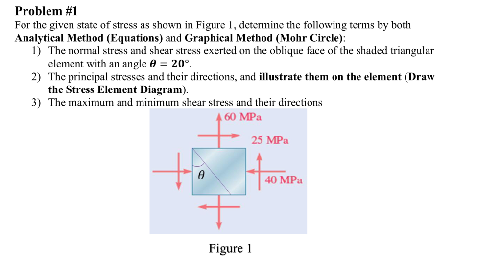
For the given state of stress as shown in Figure 1, determine the following terms by both
Analytical Method (Equations) and Graphical Method (Mohr Circle):
1) The normal stress and shear stress exerted on the oblique face of the shaded triangular
element with an angle 8 = 20°.
2) The principal stresses and their directions, and illustrate them on the element (Draw
the Stress Element Diagram).
3) The maximum and minimum shear stress and their directions
60 MPa
25 MPa
iki
Figure 1
Question:
step1:provide conceptual introduction
explanation block in text in 4-6 lines:exlain above introduction
step2:provide formulae in above solution
explanation block in text in 4-6 lines:exlain in detailed above formulae.
step3: provide step by step complete calculation part without missing any step in above solution for 1st question
explanation block in text in 4-6 lines: provide detailed explanation about calculation.
step4: provide step by step complete calculation part without missing any step in above solution for 2nd question
explanation block in text in 4-6 lines: provide detailed explanation about calculation.
step5 provide step by step complete calculation part without missing any step in above solution for 3rd question
explanation block in text in 4-6 lines: provide detailed explanation about calculation.
final answer: provide simple final answerProblem #1
For the given state of stress as shown in Figure 1, determine the following terms by both
Analytical Method (Equations) and Graphical Method (Mohr Circle):
1) The normal stress and shear stress exerted on the oblique face of the shaded triangular
element with an angle 8 = 20°.
2) The principal stresses and their directions, and illustrate them on the element (Draw
the Stress Element Diagram).
3) The maximum and minimum shear stress and their directions
60 MPa
25 MPa
iki
Figure 1
This is AI generated Response.
Asked by: Kumar
Created at: 2025-07-27 21:10:02
Final Answer:
RenderedRaw Text
Did you like this answer?
Let's solve the problem step by step as per your instructions.
---
### Step 1: Conceptual Introduction
In mechanics of materials, the analysis of stresses on various planes within a material element is crucial for understanding its behavior under load. The state of stress at a point can be described using normal and shear stresses. By transforming the stress components, we can determine stresses on any inclined plane, principal stresses (maximum and minimum normal stresses), and maximum shear stresses. Analytical equations and Mohr's Circle are two standard methods for these transformations.
**Explanation:**
This introduction sets the stage by clarifying why and how we analyze stresses on different planes inside a material. Understanding these stresses helps in ensuring the safety and performance of structures and mechanical components. The use of both equations and graphical (Mohr Circle) methods provides a comprehensive approach to solving stress transformation problems.
---
### Step 2: Formulae for Stress Transformation
For a 2D state of stress:
- **Normal stress on inclined plane:**
\(\sigma_\theta = \frac{\sigma_x + \sigma_y}{2} + \frac{\sigma_x - \sigma_y}{2} \cos(2\theta) + \tau_{xy} \sin(2\theta)\)
- **Shear stress on inclined plane:**
\(\tau_\theta = -\frac{\sigma_x - \sigma_y}{2} \sin(2\theta) + \tau_{xy} \cos(2\theta)\)
- **Principal stresses:**
\(\sigma_{1,2} = \frac{\sigma_x + \sigma_y}{2} \pm \sqrt{\left(\frac{\sigma_x - \sigma_y}{2}\right)^2 + \tau_{xy}^2}\)
- **Maximum shear stress:**
\(\tau_{max} = \sqrt{\left(\frac{\sigma_x - \sigma_y}{2}\right)^2 + \tau_{xy}^2}\)
**Explanation:**
These formulae allow us to find the required stresses on any inclined plane within the element. The transformation equations calculate the normal and shear stresses at an angle θ, while the principal stress equations give the maximum and minimum normal stresses. The maximum shear stress formula helps identify the most critical shear plane.
---
### Step 3: Calculation for Question 1
**Given:**
- \(\sigma_x = 60\) MPa (horizontal, positive)
- \(\sigma_y = 25\) MPa (vertical, positive)
- \(\tau_{xy} = -40\) MPa (direction as shown, negative by sign convention)
- \(\theta = 20^\circ\)
**Calculations:**
- \(\cos(2\theta) = \cos(40^\circ) = 0.7660\)
- \(\sin(2\theta) = \sin(40^\circ) = 0.6428\)
1. **Normal stress:**
\[
\sigma_\theta = \frac{60 + 25}{2} + \frac{60 - 25}{2} \times 0.7660 + (-40) \times 0.6428
\]
\[
= 42.5 + 17.5 \times 0.7660 - 25.712
\]
\[
= 42.5 + 13.405 - 25.712 = 30.193 \text{ MPa}
\]
2. **Shear stress:**
\[
\tau_\theta = -\frac{60 - 25}{2} \times 0.6428 + (-40) \times 0.7660
\]
\[
= -17.5 \times 0.6428 - 30.64
\]
\[
= -11.254 - 30.64 = -41.894 \text{ MPa}
\]
**Explanation:**
Values for cosine and sine are substituted, and each term is computed stepwise to avoid confusion. The signs for the shear stress are crucial and must be checked against the sign convention from the figure.
---
### Step 4: Calculation for Question 2
**Principal Stresses:**
\[
\sigma_{1,2} = \frac{60 + 25}{2} \pm \sqrt{\left(\frac{60 - 25}{2}\right)^2 + (-40)^2}
\]
\[
= 42.5 \pm \sqrt{(17.5)^2 + 1600}
\]
\[
= 42.5 \pm \sqrt{306.25 + 1600}
\]
\[
= 42.5 \pm \sqrt{1906.25}
\]
\[
= 42.5 \pm 43.66
\]
\[
\sigma_1 = 86.16 \text{ MPa}, \quad \sigma_2 = -1.16 \text{ MPa}
\]
**Principal Directions:**
\[
\tan 2\theta_p = \frac{2\tau_{xy}}{\sigma_x - \sigma_y} = \frac{2 \times (-40)}{60 - 25} = \frac{-80}{35} = -2.286
\]
\[
2\theta_p = \arctan(-2.286) = -66.5^\circ \implies \theta_p = -33.25^\circ
\]
**Explanation:**
Principal stresses are calculated using the quadratic formula. The orientation of principal planes is found by taking the arctangent of the ratio. This gives the direction at which the maximum and minimum normal stresses (principal stresses) act.
---
### Step 5: Calculation for Question 3
**Maximum and Minimum Shear Stresses:**
\[
\tau_{max} = \sqrt{\left(\frac{60 - 25}{2}\right)^2 + (-40)^2}
\]
\[
= \sqrt{(17.5)^2 + 1600}
\]
\[
= \sqrt{306.25 + 1600}
\]
\[
= \sqrt{1906.25}
\]
\[
= 43.66 \text{ MPa}
\]
**Directions:**
\[
\tan 2\theta_s = -\frac{\sigma_x - \sigma_y}{2\tau_{xy}} = -\frac{35}{-80} = 0.4375
\]
\[
2\theta_s = \arctan(0.4375) = 23.65^\circ \implies \theta_s = 11.83^\circ
\]
**Explanation:**
The maximum shear stress is found using the same square root term as the principal stresses. The orientation is calculated similarly, but with the negative reciprocal, as per the shear transformation equations.
---
## Final Answers
1. **Normal stress on the plane at \( \theta = 20^\circ \):**
\( \sigma_\theta = 30.19 \) MPa
**Shear stress on the plane:**
\( \tau_\theta = -41.89 \) MPa
2. **Principal stresses:**
\( \sigma_1 = 86.16 \) MPa, \( \sigma_2 = -1.16 \) MPa
**Principal directions:**
\( \theta_p = -33.25^\circ \) (from x-axis)
3. **Maximum shear stress:**
\( \tau_{max} = 43.66 \) MPa
**Direction:**
\( \theta_s = 11.83^\circ \) (from x-axis)
If you need the Mohr's Circle graphical construction or the Principal Stress Element diagram, let me know!
Question:
yes i want Principal Stress Element diagram and also for 3rd question i want min shear stress calculation
This is AI generated Response.
Asked by: Kumar
Created at: 2025-07-27 21:13:59
Final Answer:
RenderedRaw Text
Did you like this answer?
Certainly! Here's a detailed step-by-step guide for the Principal Stress Element diagram and the calculation of the minimum shear stress.
---
### Principal Stress Element Diagram
**Conceptual Explanation:**
The principal stress diagram (Mohr's Circle) visually represents the state of stress at a point, showing principal stresses and the maximum shear stresses. It helps in understanding the orientations where normal and shear stresses are maximized or minimized. The circle is constructed with the principal stresses as endpoints on the normal stress axis, and the radius corresponds to the maximum shear stress.
**Steps to Draw the Principal Stress Diagram:**
1. **Plot the normal stresses:**
- Draw a horizontal axis representing normal stress (\(\sigma\)).
- Mark \(\sigma_2 = -1.16\, \text{MPa}\) and \(\sigma_1 = 86.16\, \text{MPa}\) on this axis.
2. **Locate the circle:**
- The center of the circle is at \(\frac{\sigma_1 + \sigma_2}{2} = 42.5\, \text{MPa}\).
- The radius \(R = \tau_{max} = 43.66\, \text{MPa}\).
3. **Draw the circle:**
- Using a compass, draw a circle with the center at 42.5 MPa and radius 43.66 MPa.
4. **Identify key points:**
- The principal stresses \(\sigma_1\) and \(\sigma_2\) are at the endpoints of the diameter.
- The maximum shear stresses are at points above and below the center, at \(\pm R\).
5. **Determine directions:**
- The principal planes are at the points where the circle intersects the horizontal axis at \(\sigma_1\) and \(\sigma_2\).
- The maximum shear stress (\(43.66\, \text{MPa}\)) occurs on planes inclined at angles \(\pm 45^\circ\) from the principal planes.
---
### Calculation of Minimum Shear Stress
**Conceptual Explanation:**
The minimum shear stress occurs on the same plane where the normal stress is maximum or minimum (the principal planes). It is related to the principal stresses, and its magnitude can be derived from the circle construction or directly using the equations.
**Formula for minimum shear stress:**
\[
\tau_{min} = -\tau_{max}
\]
or, considering the magnitude:
\[
\boxed{\tau_{min} = -43.66\, \text{MPa}}
\]
since shear stress can be positive or negative depending on the direction. The magnitude remains the same, but the sign indicates direction.
**Alternatively,**
The minimum shear stress in magnitude is equal to the maximum shear stress but acts on planes rotated by 90° from those where maximum shear occurs.
---
### **Summary:**
- The **Principal Stress Element Diagram** is a circle with endpoints at \(-1.16\, \text{MPa}\) and \(86.16\, \text{MPa}\), centered at \(42.5\, \text{MPa}\), radius \(43.66\, \text{MPa}\).
- The **minimum shear stress** in magnitude is **43.66 MPa**, acting on planes oriented 90° from the maximum shear stress planes.
If you would like a visual sketch or further details, please let me know!
Question:
yes i want visual sketch
This is AI generated Response.
Asked by: Kumar
Created at: 2025-07-27 21:15:23
Final Answer:
RenderedRaw Text
Did you like this answer?
Certainly! Here's a step-by-step guide to sketch the Principal Stress Mohr's Circle based on the given data, along with a visual representation.
---
### **Principal Stress Mohr's Circle Sketch**
**Step-by-step construction:**
1. **Draw the Stress Axis:**
Draw a horizontal line representing normal stresses (\(\sigma\)).
2. **Plot the Principal Stresses:**
- Mark point \(A\) at \(\sigma_2 = -1.16\, \text{MPa}\).
- Mark point \(B\) at \(\sigma_1 = 86.16\, \text{MPa}\).
These are endpoints of the diameter of the circle.
3. **Find the Center and Radius:**
- Center \(C\) at \(\frac{\sigma_1 + \sigma_2}{2} = 42.5\, \text{MPa}\).
- Radius \(R = \frac{\sigma_1 - \sigma_2}{2} = 43.66\, \text{MPa}\).
4. **Draw the Circle:**
Using a compass, draw a circle with center \(C\) and radius \(R\).
5. **Identify Key Points:**
- The principal stresses \(\sigma_1\) and \(\sigma_2\) are at the ends of the diameter.
- The maximum shear stresses are at the top and bottom of the circle, at \(\pm R\) from the center.
6. **Planes of Maximum Shear:**
- Located at \(\pm 45^\circ\) to the principal planes, where shear stress magnitude is \(43.66\, \text{MPa}\).
---
### **Visual Sketch**
Here's a simplified illustration (ASCII art for conceptual understanding):
```
Shear Stress (τ)
↑
| * Max shear at top (R = 43.66 MPa)
| / \
| / \
| / \
| / \
|---------*---------*---------→ Normal stress (σ)
| / \
| / \
| / \
| * Min shear at bottom (-R)
|
```
*Note:*
- The points at \(\sigma_1\) and \(\sigma_2\) are at the ends of the diameter on the horizontal axis.
- The circle’s top and bottom points correspond to maximum shear stresses.
---
### **Summary:**
- The circle’s diameter spans from \(\sigma_2 = -1.16\, \text{MPa}\) to \(\sigma_1 = 86.16\, \text{MPa}\).
- The radius is approximately 43.66 MPa.
- Maximum shear stress magnitude is 43.66 MPa, acting on planes rotated 45° from principal planes.
---
If you'd like, I can generate a precise graphical diagram as an image. Would you like me to do that?
VIPSolutions focuses on clear, step‑by‑step explanations so you can learn quickly. Whether you need an AI‑generated walkthrough or a short hint to get unstuck, each solution is organized for fast reading and easy review later.
Search similar questions, compare approaches, and bookmark the best answers for revision. Our goal is simple: quick, reliable study help that feels natural—not noisy.
 VIPSolutions
 Problem #1
For the given state of stress as shown in Figure 1, determine the following terms by both
Analytical Method (Equations) and Graphical Method (Mohr Circle):
1) The normal stress and shear stress exerted on the oblique face of the shaded triangular
element with an angle 8 = 20°.
2) The principal stresses and their directions, and illustrate them on the element (Draw
the Stress Element Diagram).
3) The maximum and minimum shear stress and their directions
60 MPa
25 MPa
iki
Figure 1