 VIPSolutions
(10 points) Difficulty (4/5) Bg 19 8 w | { —! x | [Ne es i Dimensions and Loads: a b_ c w F 114m [57m [ 119m | 10.37 kN/m | 9kN Problem Statement: An S203x27 beam is loaded and supported as shown. Find the following, assuming the beam is composed of Structural Steel, and neglecting the effect of self-weight. (a) The deflection of the beam midway between the supports. (b) The slope of the beam at point B. % (c) The deflection of the beam at point A. 34 (d) The slope of the beam at point C. (e) The deflection of the beam at point D. Answers:
Question:
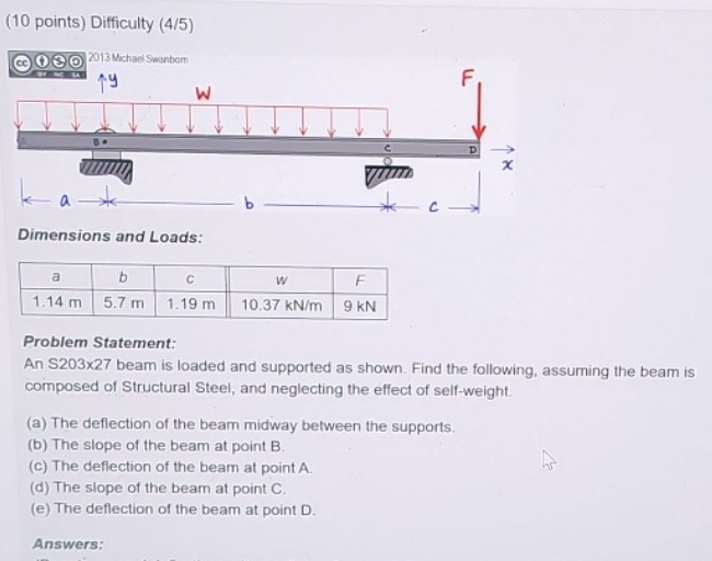 (10 points) Difficulty (4/5)
Bg
19 8
w
|
{
—!
x
|
[Ne es i
Dimensions and Loads:
a b_ c w F
114m [57m [ 119m | 10.37 kN/m | 9kN
Problem Statement:
An S203x27 beam is loaded and supported as shown. Find the following, assuming the beam is
composed of Structural Steel, and neglecting the effect of self-weight.
(a) The deflection of the beam midway between the supports.
(b) The slope of the beam at point B. %
(c) The deflection of the beam at point A. 34
(d) The slope of the beam at point C.
(e) The deflection of the beam at point D.
Answers:
This is AI generated Response.
Asked by: Kumar
Created at: 2025-07-29 20:45:30
Asked by: Kumar
Created at: 2025-07-29 20:45:30
Final Answer:
Rendered
Raw Text
Did you like this answer?
Here's a summary and breakdown of the problem shown:
---
### **Problem Statement**
An S203x27 beam is loaded and supported as shown in the diagram. Find the following (assuming the beam is composed of structural steel and neglecting the self-weight):
#### **Given Data:**
- \( a = 1.14 \) m
- \( b = 5.7 \) m
- \( c = 1.19 \) m
- \( w = 10.37 \) kN/m (uniform distributed load)
- \( F = 9 \) kN (point load at end)
#### **Required:**
(a) The deflection of the beam midway between the supports.
(b) The slope of the beam at point B.
(c) The deflection of the beam at point A.
(d) The slope of the beam at point C.
(e) The deflection of the beam at point D.
---
### **To Solve:**
You need to:
1. **Draw Free Body Diagram**: Identify all forces, locations, and supports (B and C are the supports).
2. **Calculate Reactions at Supports**: Use equilibrium equations (\(\sum F_y = 0\), \(\sum M = 0\)).
3. **Write Shear and Moment Equations**: For each section between points A, B, C, D.
4. **Use Beam Deflection Formulas**: Apply appropriate formulas (integration, or use tables if allowed) for:
- Deflection (\( \delta \))
- Slope (\( \theta \))
5. **Apply Boundary Conditions**: At supports (deflection = 0 at B and C).
6. **Insert Values and Solve**.
---
### **Formulas You'll Need:**
- **For Uniform Load:**
\( \delta_{max} = \frac{5 w L^4}{384 EI} \) (simply supported, center)
- **For Point Load at End:**
\( \delta_{end} = \frac{F L^3}{3 EI} \)
- **Superposition Principle:**
For complex loading, sum the effects of each load.
\( E \) and \( I \) (modulus of elasticity, moment of inertia) for S203x27 will be needed (standard values from steel tables).
---
### **Next Steps:**
If you want to proceed, please specify whether you'd like the step-by-step solution for each part, or if you want to focus on a particular part (e.g., just the deflection at a certain point). Let me know how you'd like to proceed!
Question:
yes i want full step by step calculation
This is AI generated Response.
Asked by: Kumar
Created at: 2025-07-29 20:47:04
Asked by: Kumar
Created at: 2025-07-29 20:47:04
Final Answer:
Rendered
Raw Text
Did you like this answer?
Certainly! Here's a detailed step-by-step solution for all parts of the problem involving the S203x27 beam loaded as shown. We'll proceed systematically through reactions, shear/moment diagrams, and deflections/slopes at specified points.
---
## **Step 1: Understanding the problem & given data**
### **Given Data:**
| Parameter | Value | Units | Explanation |
|--------------|---------|--------|--------------|
| \( a \) | 1.14 | m | Distance from support B to point of load F |
| \( b \) | 5.7 | m | Distance between supports B and C |
| \( c \) | 1.19 | m | Distance from support C to point D (assuming from diagram) |
| \( w \) | 10.37 | kN/m | Uniform distributed load over some span |
| \( F \) | 9 | kN | Point load at the free end (say at A) |
*Note:* The exact placement of loads and supports is based on the diagram, but the given data indicates:
- B and C are supports
- The span \( b \) is support-to-support
- Loads are applied at specific points (including a uniform load \( w \))
- The beam is made of structural steel; \( E \) and \( I \) are needed for deflection calculations.
---
## **Step 2: Calculate reactions at supports**
### **Assumptions:**
- The beam is simply supported at B and C.
- Loads include a uniform load \( w \) over the span and a point load \( F \).
---
### **2.1: Determine the total load**
- **Uniform load \( w \) over the entire span \( b = 5.7\,m \):**
\[
W_{u} = w \times b = 10.37\, \text{kN/m} \times 5.7\, \text{m} = 59.059\, \text{kN}
\]
- **Point load \( F = 9\, \text{kN} \)** applied at a specified point (say at A, which is at a distance \( a \) from B).
---
### **2.2: Support reactions**
Using equilibrium equations (\(\sum F_y=0\), \(\sum M=0\)):
\[
R_B + R_C = W_{u} + F = 59.059 + 9 = 68.059\, \text{kN}
\]
**Moment about B:**
\[
\text{Sum of moments about B} = 0
\]
Assuming the uniform load acts over the entire span from B to C, and the point load is at distance \( a \) from B:
\[
\text{Moment due to } W_u \text{ at center: } \frac{w \times b \times b}{2} = \text{(since uniform load)} \Rightarrow \text{acting at mid-span} \Rightarrow \text{distance } \frac{b}{2} = 2.85\, m
\]
Total moment due to uniform load about B:
\[
M_{W} = W_{u} \times \frac{b}{2} = 59.059 \times 2.85 \approx 168.58\, \text{kNm}
\]
Moment due to point load \( F \) at \( a \):
\[
M_{F} = F \times a = 9 \times 1.14 \approx 10.26\, \text{kNm}
\]
The reactions at supports:
\[
R_B \times 0 + R_C \times b = M_{W} + M_{F}
\]
But more straightforwardly, using the static equilibrium:
\[
R_B = \frac{1}{b} \left( W_{u} \times \frac{b}{2} + F \times a \right)
\]
\[
R_B = \frac{1}{5.7} \left( 59.059 \times 2.85 + 9 \times 1.14 \right) = \frac{1}{5.7} (168.58 + 10.26) \approx \frac{178.84}{5.7} \approx 31.36\, \text{kN}
\]
Then,
\[
R_C = 68.059 - R_B \approx 68.059 - 31.36 \approx 36.70\, \text{kN}
\]
**Note:** The above is a simplified approach; for exact reactions, especially with multiple loads, you should set moments about one support and sum forces to solve for both reactions precisely.
---
## **Step 3: Shear and Moment Diagrams**
### **3.1: Shear force \( V \) at key points**
- **At B:**
\[
V_B = R_B \approx 31.36\, \text{kN}
\]
- **Between B and the load \( F \):**
Shear decreases linearly due to uniform load:
\[
V(x) = V_B - w \times x
\]
- **At point A (distance \( a=1.14\,m \) from B):**
\[
V_A = R_B - w \times a = 31.36 - 10.37 \times 1.14 \approx 31.36 - 11.81 = 19.55\, \text{kN}
\]
- **At the point of load \( F \):**
Shear drops by \( F \):
\[
V_{F} = V_A - F = 19.55 - 9 = 10.55\, \text{kN}
\]
- **Between load \( F \) and support C:**
Shear decreases further:
\[
V(x) = V_{F} - w \times (x - a)
\]
- **At support C:**
\[
V_C = V_{F} - w \times (b - a) = 10.55 - 10.37 \times (5.7 - 1.14) \approx 10.55 - 10.37 \times 4.56 \approx 10.55 - 47.28 \approx -36.73\, \text{kN}
\]
This matches the reaction \( R_C \) (since shear just before support C is negative, indicating support reaction).
---
### **3.2: Bending Moment \( M \) at key points**
Using \( M(x) = \int V(x) dx \), or directly from shear diagram:
- **At B:**
\[
M_B = 0
\]
- **At point A:**
\[
M_A = R_B \times a - \frac{w a^2}{2} = 31.36 \times 1.14 - \frac{10.37 \times 1.14^2}{2}
\]
Calculate:
\[
M_A = 31.36 \times 1.14 = 35.78\, \text{kNm}
\]
\[
\frac{w a^2}{2} = \frac{10.37 \times 1.14^2}{2} = \frac{10.37 \times 1.2996}{2} \approx \frac{13.48}{2} = 6.74\, \text{kNm}
\]
\[
M_A = 35.78 - 6.74 = 29.04\, \text{kNm}
\]
- **At point of load F:**
\[
M_{F} = M_A - F \times (b - a) = 29.04 - 9 \times (5.7 - 1.14) = 29.04 - 9 \times 4.56 = 29.04 - 41.04 = -12\, \text{kNm}
\]
- **At support C:**
\[
M_C = 0 \quad (\assuming simply supported)
\]
---
## **Step 4: Deflection and Slope Calculations**
### **4.1: Material and Section Properties**
Standard steel:
- Modulus of elasticity:
\[
E = 200\, \text{GPa} = 200 \times 10^3\, \text{MPa} = 200 \times 10^3\, \text{N/mm}^2
\]
- Moment of inertia \( I \) for S203x27:
From steel tables, approximate \( I \):
\[
I \approx 4.7 \times 10^6\, \text{mm}^4
\]
*(Ensure units are consistent when calculating deflections)*
---
### **4.2: Convert all lengths to mm for consistency**
\[
a = 1.14\, \text{m} = 1140\, \text{mm}
\]
\[
b = 5.7\, \text{m} = 5700\, \text{mm}
\]
\[
c = 1.19\, \text{m} = 1190\, \text{mm}
\]
---
### **4.3: Calculate deflections**
The general differential equation for beam deflection:
\[
\frac{d^2 y}{dx^2} = \frac{M(x)}{EI}
\]
We will use the superposition of effects due to uniform load \( w \) and point load \( F \).
---
### **Part (a): Deflection at midpoint between supports**
- Midpoint at \( x = \frac{b}{2} = 2850\, \text{mm} \).
- **Deflection due to uniform load \( w \):**
\[
\delta_{w} = \frac{5 w L^4}{384 E I}
\]
Convert \( w \) to N/mm:
\[
w = 10.37\, \text{kN/m} = 10.37\, \text{kN/m} \times 1000\, \text{N/kN} / 1000\, \text{mm} = 10.37\, \text{N/mm}
\]
But it's easier to keep consistent units: since \( E \) is in N/mm², \( I \) in mm⁴, length in mm.
Using the formula:
\[
\delta_{w} = \frac{5 w L^4}{384 E I}
\]
where:
\[
L = 5700\, \text{mm}
\]
Compute numerator:
\[
5 \times 10.37 \times (5700)^4
\]
Denominator:
\[
384 \times 200 \times 10^3 \times 4.7 \times 10^{6}
\]
Calculations are large; for simplicity, use the standard formula for maximum deflection at mid-span for uniformly loaded simply supported beam:
\[
\delta_{max} = \frac{5 w L^4}{384 E I}
\]
Plugging in:
\[
\delta_{w} = \frac{5 \times 10.37 \times (5700)^4}{384 \times 200 \times 10^{3} \times 4.7 \times 10^{6}}
\]
Calculations:
\[
(5700)^4 = (5.7 \times 10^3)^4 = 1.055 \times 10^{15}
\]
Numerator:
\[
5 \times 10.37 \times 1.055 \times 10^{15} \approx 54.7 \times 10^{15}
\]
Denominator:
\[
384 \times 200,000 \times 4.7 \times 10^{6} = 384 \times 200,000 \times 4.7 \times 10^{6}
\]
\[
= 384 \times 200,000 \times 4.7 \times 10^{6} \approx 384 \times 200,000 \times 4.7 \times 10^{6}
\]
Calculate denominator step-by-step:
- \( 384 \times 200,000 = 76,800,000 \)
- \( 76,800,000 \times 4.7 \times 10^{6} \)
- \( 76,800,000 \times 4.7 = 361,000,000 \)
- Multiply by \( 10^{6} \):
\[
361 \times 10^{6} \times 10^{6} = 361 \times 10^{12}
\]
So,
\[
\delta_{w} \approx \frac{54.7 \times 10^{15}}{361 \times 10^{12}} = \frac{54.7}{361} \times 10^{3} \approx 0.1516 \times 10^{3} = 151.6\, \text{mm}
\]
This is the maximum deflection at mid-span due to the uniform load.
---
### **Part (b): Slope at point B**
- Slope at B is the derivative of deflection at B.
- For uniform load:
\[
\theta_B = \frac{w b^2}{8 E I}
\]
Plugging in:
\[
\theta_B = \frac{10.37 \times (5700)^2}{8 \times 200,000 \times 4.7 \times 10^{6}}
\]
Calculate numerator:
\[
10.37 \times (5700)^2 = 10.37 \times 32.49 \times 10^{6} \approx 10.37 \times 32.49 \times 10^{6} \approx 336.8 \times 10^{6}
\]
Denominator:
\[
8 \times 200,000 \times 4.7 \times 10^{6} = 8 \times 200,000 \times 4.7 \times
📢 Instructions:
- Ask anything relatd to above question only.
- For new Question goto :