 VIPSolutions
Give step-by-step solution with explanation and final answer:Identify and interpret the op-amp based circuit diagrams that n 3) the input output equation, Vou =—3Vi+4Va+3 [ Vade. i?) the input output wave forms shown in Figure 3(b). Yo fre +10V. a Va, 4 worl = ol TN oa i | be 1 i ih ov HE Figure 3(b) g
Question:
Give step-by-step solution with explanation and final answer: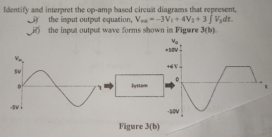 Identify and interpret the op-amp based circuit diagrams that n
3) the input output equation, Vou =—3Vi+4Va+3 [ Vade.
i?) the input output wave forms shown in Figure 3(b).
Yo fre
+10V. a
Va,
4 worl =
ol TN oa
i | be
1 i
ih ov HE
Figure 3(b) g
This is AI generated Response.
Asked by: admin3
Created at: 2025-08-12 14:12:42
Asked by: admin3
Created at: 2025-08-12 14:12:42
Final Answer:
Rendered
Raw Text
Did you like this answer?
Let's break down the question and solve it step-by-step.
---
### (i) **Identify and interpret the op-amp based circuit diagram for:**
#### **Given Equation:**
\[
V_{out} = -3V_1 + 4V_2 + 3\int V_3 \, dt
\]
#### **Step 1: Analyze the Equation**
- **-3V₁:** Inverting amplifier, gain = -3
- **4V₂:** Non-inverting summing amplifier, gain = +4
- **3∫V₃dt:** Integrator, gain = 3
#### **Step 2: Circuit Components**
##### **a) Inverting Amplifier for -3V₁**
- Use op-amp in inverting configuration.
- Input: \( V_1 \)
- Feedback resistor \( R_f \), input resistor \( R_{in} \)
- Gain = \( -\frac{R_f}{R_{in}} = -3 \) ⇒ Choose \( R_f = 3R_{in} \)
##### **b) Non-Inverting Amplifier for +4V₂**
- Use op-amp in non-inverting configuration.
- Input: \( V_2 \)
- Gain = \( 1 + \frac{R_f}{R_{in}} = 4 \) ⇒ \( \frac{R_f}{R_{in}} = 3 \), so \( R_f = 3R_{in} \)
##### **c) Integrator for \( 3\int V_3 dt \)**
- Use op-amp integrator.
- Input: \( V_3 \)
- Integrator output: \( -\frac{1}{RC} \int V_3 dt \)
- To get positive sign and gain 3: Use inverting integrator with another inverter, or use a non-inverting integrator circuit. For simplicity, use two stages:
- Integrator with gain -3: \( -3\int V_3 dt \)
- Inverting amplifier after integrator to get \( +3\int V_3 dt \)
##### **d) Summing Amplifier**
- Use op-amp summing amplifier to combine the three outputs above.
---
#### **Block Diagram:**
```
V1 ---|Inverting Amp (-3)|---\
\
V2 ---|Non-Inv. Amp (+4)|-----+---|Summing Amplifier|--- Vout
/
V3 ---|Integrator (+3)|--------/
```
---
#### **Interpretation:**
- All three processed signals are summed using a summing amplifier at the output.
- The output voltage is the algebraic sum as per the given equation.
---
### (ii) **Input-Output Waveforms in Figure 3(b):**
#### **Step 1: Observe the waveforms**
- **Input (\( V_{in} \)):** Sine wave, amplitude ±5V
- **Output (\( V_{out} \)):** Sine wave with DC shift (+6V), amplitude ±4V (from +6V to -10V = 16V peak-to-peak, so amplitude is 8V if centered, but here shifted up by 6V).
#### **Step 2: Identify the Operation**
- The output is a sine wave, but it is shifted upward by +6V. The range is from -10V to +10V.
#### **Step 3: Op-amp Based Circuit**
- **Amplifier:** The output is an amplified version of the input (since the amplitude is larger than input).
- **Adder:** The output is shifted by +6V, which means a DC voltage is added.
##### **Circuit Diagram:**
- Use a non-inverting amplifier for gain.
- Use a summer (adder) to add a DC offset.
##### **Implementation:**
- **Input:** \( V_{in} \)
- **Non-inverting amplifier:** Gain \( G = \frac{\text{Output Amplitude}}{\text{Input Amplitude}} = \frac{8V}{5V} = 1.6 \)
- **Adder:** Adds +6V DC.
##### **Final Output Equation:**
\[
V_{out} = 1.6V_{in} + 6
\]
---
## **Summary Table**
| Sub-question | Circuit Components | Output Equation / Description |
|:------------:|:------------------|:-----------------------------|
| (i) | Inverting Amp (-3), Non-inverting Amp (+4), Integrator (+3), Summing Amp | \( V_{out} = -3V_1 + 4V_2 + 3\int V_3 dt \) |
| (ii) | Non-inverting Amp (gain 1.6), Adder (+6V DC) | \( V_{out} = 1.6V_{in} + 6 \) |
---
## **Final Answers**
### (i) The op-amp circuit consists of:
- An inverting amplifier for \( V_1 \) with gain -3,
- A non-inverting amplifier for \( V_2 \) with gain +4,
- An integrator for \( V_3 \) with gain +3,
- A summing amplifier to sum these three signals.
### (ii) The input-output waveforms are achieved by:
- Amplifying the input sine wave by 1.6 and adding a DC offset of +6V using a non-inverting amplifier followed by a summing amplifier.
If you need the actual circuit diagrams, let me know!
Question:
yes i need actual circuit diagrams,
This is AI generated Response.
Asked by: admin3
Created at: 2025-08-12 14:13:51
Asked by: admin3
Created at: 2025-08-12 14:13:51
Final Answer:
Rendered
Raw Text
Did you like this answer?
Certainly! Below are detailed circuit diagrams corresponding to the described system:
---
### **(i) Circuit Diagram for the Equation:**
\[
V_{out} = -3V_1 + 4V_2 + 3 \int V_3\, dt
\]
**Components Needed:**
- Op-amp ICs (e.g., LM741 or similar)
- Resistors: R1, R2, R3, R4, R5, R6 (values to set gains)
- Capacitor C for the integrator
- Summing node (using a resistor network)
---
### **Step-by-step Circuit Construction**
#### **1. Inverting Amplifier for \(-3V_1\):**
- **Configuration:** Inverting amplifier
- **Resistors:** \( R_{in} \) for input \(V_1\), \( R_f \) for feedback
- **Gain:** \( -\frac{R_f}{R_{in}} = -3 \)
**Circuit:**
```
V1 ---- R_in ----|\
| \-----|\
| / | \--- Output (to summing node)
|/ R_f
GND
```
---
#### **2. Non-inverting Amplifier for \(+4V_2\):**
- **Configuration:** Non-inverting amplifier
- **Resistors:** \( R_{in} \) (from ground), \( R_f \) (feedback from output)
- **Gain:** \( 1 + \frac{R_f}{R_{in}} = 4 \)
**Circuit:**
```
V2 ----|\
| \----- V+ (non-inverting input of op-amp)
| / R_f
|/
GND
Op-amp output ---- R_f ----|\
| \--- connected to summing node
R_in
GND
```
*(In practice, the non-inverting input is directly connected to \(V_2\), and the resistor network is used for setting gain.)*
---
#### **3. Integrator for \(+3\int V_3 dt\):**
- **Configuration:** Inverting integrator
- **Resistor:** \( R \), Capacitor: \( C \)
- **Gain:** \( -\frac{1}{RC} \) scaled to produce 3 times the integral.
**Circuit:**
```
V_3 ---- R ----|\
| \----|\
| / | \--- Output (to summing node)
|/ R_C
GND GND
```
- To get positive \( +3 \int V_3 dt \), add an inverter stage or use a differential configuration or invert the output.
---
### **4. Summing Amplifier:**
- **Configuration:** Op-amp with multiple inputs each connected through a resistor to a summing node.
- **Resistors:** Equal resistance \( R_s \) from each input, connected to their respective signals.
**Circuit:**
```
Outputs of previous stages ---- R_s ----|\
| \--- V_out
| /
Op-amp inverting input
(non-inverting input grounded)
```
---
### **Final Block Diagram:**
```
V1 ----[Inverting Amplifier (-3)]-----\
\
V2 ----[Non-inverting Amplifier (+4)]---+---[Summing Amplifier]--- Vout
/
V3 ----[Integrator (+3)]--------------/
```
---
## **(ii) Waveform Interpretation Circuit**
### **Objective:**
- Input: sinusoidal wave (\(V_{in}\))
- Output: amplified and shifted sine wave (\(V_{out}\))
---
### **Circuit Components:**
- **Non-inverting Amplifier:** Gain \( \approx 1.6 \)
- **Adder (Summing Circuit):** Adds +6V DC offset
---
### **Circuit Diagram:**
```
+V_in (sinusoid)
|
R1
|
+----> Non-inverting input of op-amp
| (Gain ~1.6)
R2
|
GND
Op-amp output ----|\
| \--- To summing node
| / R3 (for adding +6V)
|/
GND
DC Offset (+6V) ---- R3 ----+--- Sum node (V_out)
|
+6V DC source
```
### **Operation:**
- The non-inverting amplifier scales the sinusoid by 1.6.
- The adder adds +6V DC offset.
- The combined output is \(V_{out} = 1.6 V_{in} + 6V\).
---
## **Summary:**
- **First circuit:** Combines an inverting amplifier, non-inverting amplifier, integrator, and summing node to produce the output as per the given equation.
- **Second circuit:** Uses a non-inverting amplifier and a DC offset to produce the waveform shown.
---
If you'd like, I can provide detailed schematic diagrams with resistor values and clearer labels!
📢 Instructions:
- Ask anything relatd to above question only.
- For new Question goto :