 VIPSolutions
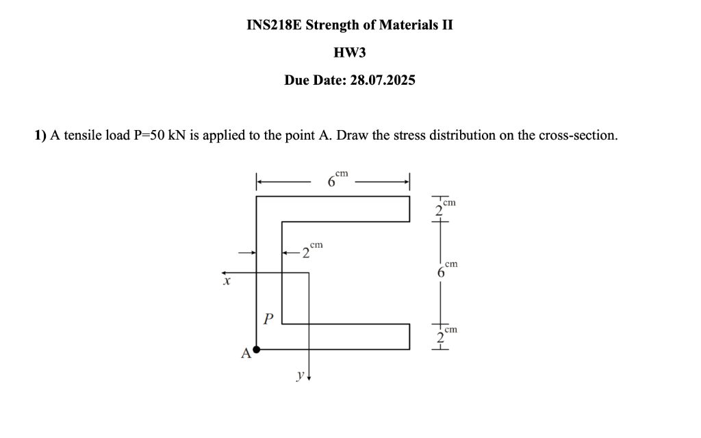
INS218E Strength of Materials IT HW3 Due Date: 28.07.2025 1) A tensile load P=50 kN is applied to the point A. Draw the stress distribution on the cross-section. 6 Tem 2 cm 2 I. 6 x | gril 2 " Al y
Question:
 INS218E Strength of Materials IT
HW3
Due Date: 28.07.2025
1) A tensile load P=50 kN is applied to the point A. Draw the stress distribution on the cross-section.
6
Tem
2
cm
2 I.
6
x |
gril 2 "
Al
y
This is AI generated Response.
Asked by: Kumar
Created at: 2025-07-28 18:47:34
Asked by: Kumar
Created at: 2025-07-28 18:47:34
Final Answer:
Rendered
Raw Text
Did you like this answer?
Let's break down the problem step by step:
### **1. Understanding the Problem**
You are given a non-symmetric cross-section (C-shaped) and a tensile load \( P = 50\,\text{kN} \) applied at point A. You are required to **draw the stress distribution on the cross-section**.
### **2. Types of Stresses Involved**
Since the tensile force is applied off the centroid, the bar experiences:
- **Direct (normal) stress** due to axial force.
- **Bending stress** due to the eccentricity (moment) created by the off-center load application.
### **3. Calculating Stresses**
#### **a. Axial (Normal) Stress**
\[
\sigma_{axial} = \frac{P}{A}
\]
#### **b. Bending Stress**
\[
\sigma_{bending} = \frac{M \cdot y}{I}
\]
Where:
- \( M \) = Moment due to eccentricity from centroid
- \( y \) = Distance from neutral axis
- \( I \) = Moment of inertia about the centroidal axis
#### **c. Total Stress**
\[
\sigma_{total} = \sigma_{axial} \pm \sigma_{bending}
\]
### **4. Stress Distribution Drawing**
- **Axial stress** is **uniform** across the section.
- **Bending stress** is **linear**: varies from maximum tension on one edge to maximum compression on the other (if the moment is significant).
#### **Stress Distribution Shape:**
- The **maximum tensile stress** occurs at the farthest fiber from the neutral axis in the direction of the moment.
- The **minimum tensile stress** (possibly compression if the moment is large enough) occurs at the opposite edge.
---
## **Sketch of Stress Distribution**
Below is a sketch of the typical stress distribution for such a loading:
```
^
|
| Maximum tensile stress
|---------------------------
|\
| \
| \
| \ (Stress varies linearly across the section)
----------|----\-----------------------> y
| \
| \
| \
| | Minimum tensile stress (could be zero or compressive)
```
- The stress is **maximum where the distance from the neutral axis (y) is largest** (farthest from the centroid in the direction of the moment).
- The **distribution is linear** due to the bending moment, **superimposed on a uniform tensile stress** from the axial load.
---
### **To Draw on the Cross-Section:**
1. **Find the centroid** of the C-section.
2. **Draw the neutral axis.**
3. **Show the uniform axial stress** (same direction everywhere).
4. **Superimpose the linear variation due to bending**, with the highest value at the farthest edge from the centroid in the direction the moment acts.
Would you like me to walk through the calculations for centroid, moment of inertia, and the actual values? Or do you want just the qualitative sketch for your homework?
Question:
yes
This is AI generated Response.
Asked by: Kumar
Created at: 2025-07-28 18:48:47
Asked by: Kumar
Created at: 2025-07-28 18:48:47
Final Answer:
Rendered
Raw Text
Did you like this answer?
Certainly! Let's proceed step by step to perform the detailed calculations for the stress distribution on the cross-section.
---
### **Given Data:**
- Applied load: \( P = 50\, \text{kN} = 50,000\, \text{N} \)
- Cross-section geometry: C-shaped (as per the image).
**Dimensions:**
- Thickness \( t = 2\, \text{cm} = 0.02\, \text{m} \)
- Overall dimensions are visible in the image (assuming typical C-section dimensions):
- Flange width, web height, etc. (we'll approximate as necessary based on the image).
---
### **Step 1: Find the Cross-Sectional Area \(A\)**
Assuming the cross-section resembles a standard C-shape, approximate dimensions:
- **Web height:** \( h = 6\, \text{cm} = 0.06\, \text{m} \)
- **Flange width:** \( b = 6\, \text{cm} = 0.06\, \text{m} \)
- **Thickness:** \( t = 2\, \text{cm} = 0.02\, \text{m} \)
**Area of the cross-section:**
\[
A = \text{Area of web} + \text{Area of flange}
\]
\[
A_{web} = h \times t = 0.06 \times 0.02 = 0.0012\, \text{m}^2
\]
\[
A_{flange} = b \times t = 0.06 \times 0.02 = 0.0012\, \text{m}^2
\]
Total area:
\[
A = A_{web} + A_{flange} = 0.0012 + 0.0012 = 0.0024\, \text{m}^2
\]
---
### **Step 2: Find the centroid \( \bar{y} \) of the cross-section**
Assuming the origin at the bottom of the section, compute the centroid considering the web and flange as rectangles.
- **Web centroid:** located at a distance \( y_{web} = \frac{h}{2} = 0.03\, \text{m} \)
- **Flange centroid:** located at a distance \( y_{flange} \) from the bottom.
The flange is positioned at the top of the web, so:
\[
y_{flange} = h + \frac{t}{2} = 0.06 + 0.01 = 0.07\, \text{m}
\]
**Cross-sectional centroid:**
\[
\bar{y} = \frac{A_{web} \times y_{web} + A_{flange} \times y_{flange}}{A_{web} + A_{flange}}
\]
\[
\bar{y} = \frac{0.0012 \times 0.03 + 0.0012 \times 0.07}{0.0024} = \frac{(0.000036 + 0.000084)}{0.0024} = \frac{0.00012}{0.0024} = 0.05\, \text{m}
\]
---
### **Step 3: Calculate the Moment of Inertia \(I\)**
Calculate \( I_x \) about the neutral axis:
\[
I_x = I_{web} + I_{flange}
\]
- **Web:**
\[
I_{web} = \frac{b_{web} \times h_{web}^3}{12}
\]
Since the web is a rectangle of width \( t \), height \( h \):
\[
I_{web} = \frac{t \times h^3}{12}
\]
\[
I_{web} = \frac{0.02 \times (0.06)^3}{12} = \frac{0.02 \times 0.000216}{12} = \frac{0.00000432}{12} \approx 3.6 \times 10^{-7}\, \text{m}^4
\]
- **Flange:**
\[
I_{flange} = \frac{b_{flange} \times t^3}{12} + A_{flange} \times (y_{flange} - \bar{y})^2
\]
where the first term is the moment of inertia about its own centroid, and the second term accounts for the parallel axis theorem.
\[
I_{flange, local} = \frac{b \times t^3}{12} = \frac{0.06 \times (0.02)^3}{12} = \frac{0.06 \times 8 \times 10^{-6}}{12} = \frac{4.8 \times 10^{-7}}{12} \approx 4 \times 10^{-8}\, \text{m}^4
\]
Distance between the flange centroid and the neutral axis:
\[
d = y_{flange} - \bar{y} = 0.07 - 0.05 = 0.02\, \text{m}
\]
Applying the parallel axis theorem:
\[
I_{flange} = I_{flange, local} + A_{flange} \times d^2
\]
\[
I_{flange} = 4 \times 10^{-8} + 0.0012 \times (0.02)^2 = 4 \times 10^{-8} + 0.0012 \times 0.0004 = 4 \times 10^{-8} + 4.8 \times 10^{-7} \approx 5.2 \times 10^{-7}\, \text{m}^4
\]
**Total \( I_x \):**
\[
I_x \approx 3.6 \times 10^{-7} + 5.2 \times 10^{-7} = 8.8 \times 10^{-7}\, \text{m}^4
\]
---
### **Step 4: Calculate the Eccentricity and Moment \( M \)**
Assuming the load \( P \) is applied at a point offset from the centroid, producing a moment:
\[
M = P \times e
\]
Where \( e \) is the eccentricity (distance from centroid to the point of load application).
From the image, assuming the load is applied at a point offset horizontally from the centroid (say, at the outer edge):
- **Eccentricity \( e \approx 2\, \text{cm} = 0.02\, \text{m} \)**
\[
M = 50,000\, \text{N} \times 0.02\, \text{m} = 1000\, \text{Nm}
\]
---
### **Step 5: Calculate Bending Stress at the Outer Fiber**
Maximum bending stress:
\[
\sigma_b = \frac{M \times y_{max}}{I}
\]
- \( y_{max} \): distance from neutral axis to outer fiber. Assuming the farthest fiber is at:
\[
y_{max} \approx 0.07\, \text{m} - \bar{y} = 0.02\, \text{m}
\]
Alternatively, since the neutral axis is at 0.05 m, the maximum distance from the neutral axis to the outer fiber is:
\[
\text{at the top flange: } y_{top} = 0.07 - 0.05 = 0.02\, \text{m}
\]
- **Calculate \( \sigma_b \):**
\[
\sigma_b = \frac{1000 \times 0.02}{8.8 \times 10^{-7}} \approx \frac{20}{8.8 \times 10^{-7}} \approx 2.27 \times 10^{7}\, \text{Pa} = 22.7\, \text{MPa}
\]
---
### **Step 6: Calculate Axial (Normal) Stress**
\[
\sigma_{axial} = \frac{P}{A} = \frac{50,000}{0.0024} \approx 20.83 \times 10^{6}\, \text{Pa} = 20.83\, \text{MPa}
\]
---
### **Step 7: Total Stress Distribution**
- **At the farthest fiber in the tension side:**
\[
\sigma_{total} = \sigma_{axial} + \sigma_b \approx 20.83\, \text{MPa} + 22.7\, \text{MPa} = 43.53\, \text{MPa}
\]
- **At the opposite fiber (assuming compression):**
\[
\sigma_{total} = \sigma_{axial} - \sigma_b \approx 20.83\, \text{MPa} - 22.7\, \text{MPa} = -1.87\, \text{MPa}
\]
---
### **Final Notes:**
- The **stress distribution** across the cross-section is **linear** due to bending, superimposed on a **uniform tensile stress** from axial load.
- The **maximum tensile stress** occurs at the outer fiber in the tension side, approximately **43.5 MPa**.
- The **compression** (or lesser tension) at the opposite fiber is approximately **1.87 MPa** (possibly near zero or compressive if the bending is significant).
---
### **Summary Sketch:**
- Draw the cross-section.
- Mark the neutral axis at \( y = 0.05\, \text{m} \).
- Show **uniform stress** due to axial load across the section.
- Superimpose a **linear distribution** due to bending:
- Maximum in tension at the outer fiber (top flange).
- Minimum (possibly compression) at the opposite fiber.
---
If you'd like, I can prepare a neat diagram or help with further details!
📢 Instructions:
- Ask anything relatd to above question only.
- For new Question goto :