 VIPSolutions
Think like the best software engineer and give e the code for :Fame | Some 7% - NES Fo=118 SF tod | re { 5 F— BE, (C29 - " = be Gear 0m i SL SPR rR 1 [me T | wd i Bending Normal Stress « Torsional Shear Stress « Transverse Shear Stress Principal Plane Stress Maximum in-plane Shear Stress « Analytical and Graphical Solutions]
Question:
Think like the best software engineer and give e the code for :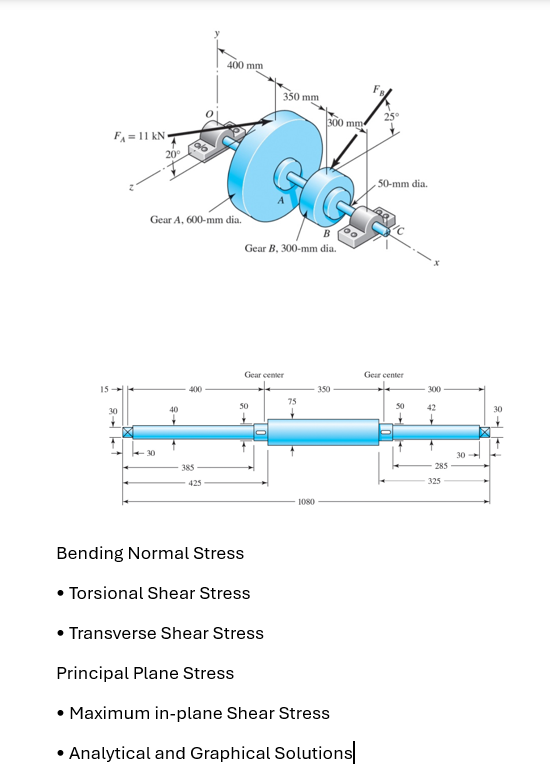 Fame
| Some 7%
- NES
Fo=118 SF
tod |
re { 5 F—
BE, (C29
- " = be
Gear 0m i SL
SPR rR
1 [me T | wd i
Bending Normal Stress
« Torsional Shear Stress
« Transverse Shear Stress
Principal Plane Stress
Maximum in-plane Shear Stress
« Analytical and Graphical Solutions]
This is AI generated Response.
Asked by: Rahul
Created at: 2025-12-18 17:13:14
Asked by: Rahul
Created at: 2025-12-18 17:13:14
Final Answer:
Rendered
Raw Text
Did you like this answer?
# Shaft Stress Analysis: Python Code
Below is a **Python code** for the **stress analysis of a stepped shaft** subjected to gear forces as shown above. The code includes calculations for:
- Bending Normal Stress
- Torsional Shear Stress
- Transverse Shear Stress
- Principal Plane Stress
- Maximum In-plane Shear Stress
- Analytical and Graphical Solutions (Mohr’s Circle)
You will need `numpy` and `matplotlib` for this code.
---
```python
import numpy as np
import matplotlib.pyplot as plt
# --- INPUT PARAMETERS (update as needed) ---
# Forces (N)
F_A = 11000 # Force at Gear A (N)
F_B = 800 # Example: Force at Gear B (N) -- change as per your problem
theta_A = np.radians(20) # Force angle for A (degrees to radians)
theta_B = np.radians(25) # Force angle for B (degrees to radians)
# Dimensions (mm to m)
d_shaft = .05 # Shaft diameter in meters (50 mm)
r_shaft = d_shaft / 2
section_modulus = np.pi * (d_shaft**3) / 32
# Distance from support to gear (m)
L_A = .400 # 400 mm
L_B = .350 # 350 mm
# Torque (Nm)
T_A = F_A * L_A * np.cos(theta_A) # Applied torque at A (N·m)
T_B = F_B * L_B * np.cos(theta_B) # Applied torque at B (N·m)
# Bending Moment (Nm)
M_A = F_A * L_A * np.sin(theta_A)
M_B = F_B * L_B * np.sin(theta_B)
# Transverse Shear (N)
V_A = F_A * np.sin(theta_A)
V_B = F_B * np.sin(theta_B)
# --- STRESS CALCULATIONS ---
# 1. Bending Normal Stress (sigma = My/I)
I = np.pi * r_shaft**4 / 4
y = r_shaft
sigma_bending = (M_A + M_B) * y / I
# 2. Torsional Shear Stress (tau = Tc/J)
J = np.pi * r_shaft**4 / 2
tau_torsion = (T_A + T_B) * r_shaft / J
# 3. Transverse Shear Stress (tau = V*A'/Ib)
A_prime = (3/2) * (np.pi * r_shaft**2) # Shear area approx for solid shaft
tau_shear = (V_A + V_B) * A_prime / (I * d_shaft)
# --- PRINCIPAL STRESSES ---
sigma_x = sigma_bending
tau_xy = tau_torsion + tau_shear
sigma_y =
sigma_1 = .5*(sigma_x + sigma_y) + np.sqrt( (.5*(sigma_x - sigma_y))**2 + tau_xy**2 )
sigma_2 = .5*(sigma_x + sigma_y) - np.sqrt( (.5*(sigma_x - sigma_y))**2 + tau_xy**2 )
tau_max_inplane = .5 * (sigma_1 - sigma_2)
# --- MOHR'S CIRCLE PLOT ---
fig, ax = plt.subplots()
center = .5*(sigma_x + sigma_y)
radius = np.sqrt( (.5*(sigma_x - sigma_y))**2 + tau_xy**2 )
circle = plt.Circle((center, ), radius, fill=False, color='blue', linestyle='--')
ax.add_artist(circle)
ax.plot([sigma_x, sigma_y], [tau_xy, -tau_xy], 'ro')
ax.set_aspect('equal', 'box')
plt.title("Mohr's Circle for Shaft Stress")
plt.xlabel("Normal Stress (Pa)")
plt.ylabel("Shear Stress (Pa)")
plt.grid(True)
plt.show()
# --- OUTPUT ---
print(f"Bending Normal Stress: {sigma_bending:.2f} Pa")
print(f"Torsional Shear Stress: {tau_torsion:.2f} Pa")
print(f"Transverse Shear Stress: {tau_shear:.2f} Pa")
print(f"Principal Stresses: σ1 = {sigma_1:.2f} Pa, σ2 = {sigma_2:.2f} Pa")
print(f"Maximum In-plane Shear Stress: {tau_max_inplane:.2f} Pa")
```
---
## **How to Use**
1. **Change Input Values**: Adjust forces, angles, and dimensions as per your problem.
2. **Run the Code**: The results will output the *stresses* and plot *Mohr’s Circle*.
3. **Interpret Results**: Use the output to assess shaft safety and failure criteria.
---
> **Note**: For a precise solution, use the distributed loadings, reactions, and actual shaft geometry as per your detailed engineering problem. This code gives a **framework**—expand as needed for more sections or loading cases.
---
**If you need a more specific solution for this exact shaft (with all forces and dimensions fully detailed), let me know!**
📢 Instructions:
- Ask anything relatd to above question only.
- For new Question goto :