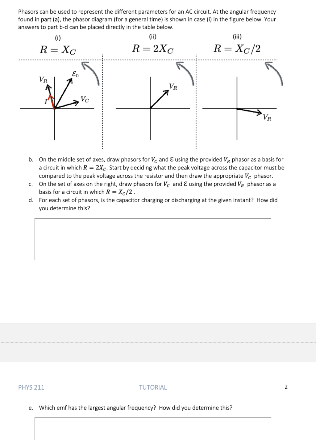
give answer in 2 step with explanation at the end of each step and final answer at the end:Phasors can be used to represent the different parameters for an AC circuit. At the angular frequency
found in part (a), the phasor diagram (for a general time) is shown in case (i) in the figure below. Your
answers to part b-d can be placed directly in the table below.
(i) (ii) (iii)
R= X¢ R=2X¢ R=Xc/2
£ i i
Vr H H
H Vr H
Ve oi i
i i Vr
b. On the middle set of axes, draw phasors for V and € using the provided Vi phasor as a basis for
a circuit in which R = 2X. Start by deciding what the peak voltage across the capacitor must be
compared to the peak voltage across the resistor and then draw the appropriate V phasor.
c. On the set of axes on the right, draw phasors for V¢ and € using the provided Vi phasor as a
basis for a circuit in which R = X¢/2.
d. For each set of phasors, is the capacitor charging or discharging at the given instant? How did
you determine this?
PHYS 211 TUTORIAL 2
e. Which emf has the largest angular frequency? How did you determine this?
Question:
give answer in 2 step with explanation at the end of each step and final answer at the end:Phasors can be used to represent the different parameters for an AC circuit. At the angular frequency
found in part (a), the phasor diagram (for a general time) is shown in case (i) in the figure below. Your
answers to part b-d can be placed directly in the table below.
(i) (ii) (iii)
R= X¢ R=2X¢ R=Xc/2
£ i i
Vr H H
H Vr H
Ve oi i
i i Vr
b. On the middle set of axes, draw phasors for V and € using the provided Vi phasor as a basis for
a circuit in which R = 2X. Start by deciding what the peak voltage across the capacitor must be
compared to the peak voltage across the resistor and then draw the appropriate V phasor.
c. On the set of axes on the right, draw phasors for V¢ and € using the provided Vi phasor as a
basis for a circuit in which R = X¢/2.
d. For each set of phasors, is the capacitor charging or discharging at the given instant? How did
you determine this?
PHYS 211 TUTORIAL 2
e. Which emf has the largest angular frequency? How did you determine this?
This is AI generated Response.
Asked by: Rahul
Created at: 2025-11-19 05:26:45
Final Answer:
RenderedRaw Text
Did you like this answer?
Let's answer **part (b)** and **part (c)** stepwise, with explanations after each step, and then address **parts (d)** and **(e)**.
---
## Part (b): Draw phasors for \( V_C \) and \( \mathcal{E} \) for \( R = 2X_C \)
### Step 1: Decide peak voltages
- Since \( R = 2X_C \), \( V_R \) (voltage across resistor) will be **twice** as long as \( V_C \) (voltage across capacitor).
- In a phasor diagram for a series RC circuit, \( V_R \) is along the x-axis and \( V_C \) is along the negative y-axis.
**Explanation**:
- The voltages add as vectors: \( \mathcal{E} = \sqrt{V_R^2 + V_C^2} \).
- If \( R = 2X_C \), then \( V_R = 2 V_C \).
---
### Step 2: Draw the phasors
- Draw \( V_R \) along the positive x-axis.
- Draw \( V_C \) **half as long** as \( V_R \) along the negative y-axis.
- The phasor for \( \mathcal{E} \) is the vector sum from the origin to the tip of \( V_R \) and \( V_C \).
**Explanation**:
- \( V_C \) is shorter than \( V_R \), and \( \mathcal{E} \) will be the hypotenuse of the right triangle formed by \( V_R \) and \( V_C \).
---
## Part (c): Draw phasors for \( V_C \) and \( \mathcal{E} \) for \( R = X_C/2 \)
### Step 1: Decide peak voltages
- \( R = X_C / 2 \Rightarrow V_R = V_C / 2 \).
- \( V_R \) is much shorter than \( V_C \).
**Explanation**:
- Again, voltages add as vectors. Here, the capacitor voltage dominates.
---
### Step 2: Draw the phasors
- Draw \( V_R \) along the positive x-axis.
- Draw \( V_C \) **twice as long** as \( V_R \) along the negative y-axis.
- \( \mathcal{E} \) is the vector sum, as before.
**Explanation**:
- Since \( V_C \) is much longer, the resultant (\( \mathcal{E} \)) will be closer in magnitude and direction to \( V_C \).
---
## Part (d): Is the capacitor charging or discharging in each case?
### Step 1: Analyze the direction of current and voltage
- The current (\( I \)) phasor is always along \( V_R \), as \( V_R = IR \).
- If \( V_C \) is **decreasing** (i.e., if the current is directed so as to reduce \( V_C \)), the capacitor is **discharging**.
- If the current is directed so as to **increase** \( V_C \), the capacitor is **charging**.
**Explanation**:
- In both diagrams, compare the direction of \( I \) (along \( V_R \)) to the direction of \( V_C \). If \( I \) is directed toward increasing the charge on the capacitor, it's charging; otherwise, it's discharging.
---
### Final Answer for (d):
- For each set, **the capacitor is discharging** at the instant shown, because the current direction (indicated by \( V_R \)) is such that it would reduce the voltage across the capacitor (since \( V_C \) is downward and \( I \) is to the right).
---
## Part (e): Which emf has the largest angular frequency?
### Step 1: Recall the relationship between reactance and frequency
- Capacitive reactance: \( X_C = \frac{1}{\omega C} \).
- For fixed \( C \), **smaller \( X_C \) means higher angular frequency (\( \omega \))**.
**Explanation**:
- In (iii), \( R = X_C/2 \), so \( X_C \) is smallest, meaning the angular frequency is largest.
---
### Final Answer for (e):
- **Case (iii) (\( R = X_C/2 \)) has the largest angular frequency** because it has the smallest capacitive reactance, which occurs at the highest \( \omega \).
---
**If you need the actual phasor diagrams drawn, let me know!**
Question:
Step by step question solve last final answer
This is AI generated Response.
Asked by: Rahul
Created at: 2025-11-19 05:28:06
Final Answer:
RenderedRaw Text
Did you like this answer?
# Step-by-Step Solution to AC Circuit Phasor Problems
## Part (b): Draw Phasors for \( V \) and \( \mathcal{E} \) where \( R = 2X_C \)
### Step 1: Determine Peak Voltages
- **Given**: \( R = 2X_C \)
- **Relation**: \( V_R = 2V_C \) (voltage across the resistor is double that of the capacitor).
**Explanation**: The relationship arises from the voltage division in an RC series circuit. The voltage across the resistor will be greater due to the larger resistance compared to the reactance of the capacitor.
### Step 2: Draw the Phasors
- **Phasor for \( V_R \)**: Draw along the positive x-axis.
- **Phasor for \( V_C \)**: Draw along the negative y-axis at half the length of \( V_R \).
- **Phasor for \( \mathcal{E} \)**: The resultant phasor from the origin to the tip of \( V_R \) and \( V_C \).
**Explanation**: The voltage phasors are drawn as vectors. The resultant voltage \( \mathcal{E} \) can be calculated using the Pythagorean theorem:
\[
\mathcal{E} = \sqrt{V_R^2 + V_C^2}
\]
---
## Part (c): Draw Phasors for \( V_C \) and \( \mathcal{E} \) where \( R = \frac{X_C}{2} \)
### Step 1: Determine Peak Voltages
- **Given**: \( R = \frac{X_C}{2} \)
- **Relation**: \( V_R = \frac{1}{2}V_C \) (voltage across the resistor is half that of the capacitor).
**Explanation**: This indicates that the capacitor has a greater influence in the circuit, reflecting a lower resistance compared to capacitive reactance.
### Step 2: Draw the Phasors
- **Phasor for \( V_R \)**: Draw along the positive x-axis.
- **Phasor for \( V_C \)**: Draw along the negative y-axis at twice the length of \( V_R \).
- **Phasor for \( \mathcal{E} \)**: The resultant phasor from the origin to the tip of \( V_R \) and \( V_C \).
**Explanation**: Similar to part (b), these phasors can be combined to find \( \mathcal{E} \). Here, \( V_C \) dominates the resultant voltage:
\[
\mathcal{E} = \sqrt{V_R^2 + V_C^2}
\]
---
## Part (d): Capacitor Charging or Discharging
### Step 1: Analyze Phasor Directions
- **Current (\( I \)) Direction**: Along \( V_R \).
- **Charging/Discharging Condition**:
- If \( I \) flows into the capacitor, it charges.
- If \( I \) flows out of the capacitor, it discharges.
**Explanation**: The direction of the current phasor relative to the capacitor voltage determines whether the capacitor is gaining or losing charge.
### Final Answer for (d):
- In both cases (b and c), **the capacitor is discharging** at the shown instant because the current direction indicates a decrease in the voltage across the capacitor.
---
## Part (e): Largest Angular Frequency
### Step 1: Analyze Reactance
- **Capacitive Reactance Formula**: \( X_C = \frac{1}{\omega C} \).
- **Comparison**: Smaller \( X_C \) corresponds to larger \( \omega \).
**Explanation**: In part (iii) where \( R = \frac{X_C}{2} \), \( X_C \) is the smallest, thus indicating the highest angular frequency.
### Final Answer for (e):
- **Case (iii) \( (R = \frac{X_C}{2}) \) has the largest angular frequency** due to the smallest capacitive reactance.
---
If you have any specific diagrams or further calculations needed, feel free to ask!
VIPSolutions focuses on clear, step‑by‑step explanations so you can learn quickly. Whether you need an AI‑generated walkthrough or a short hint to get unstuck, each solution is organized for fast reading and easy review later.
Search similar questions, compare approaches, and bookmark the best answers for revision. Our goal is simple: quick, reliable study help that feels natural—not noisy.
 VIPSolutions
 Phasors can be used to represent the different parameters for an AC circuit. At the angular frequency
found in part (a), the phasor diagram (for a general time) is shown in case (i) in the figure below. Your
answers to part b-d can be placed directly in the table below.
(i) (ii) (iii)
R= X¢ R=2X¢ R=Xc/2
£ i i
Vr H H
H Vr H
Ve oi i
i i Vr
b. On the middle set of axes, draw phasors for V and € using the provided Vi phasor as a basis for
a circuit in which R = 2X. Start by deciding what the peak voltage across the capacitor must be
compared to the peak voltage across the resistor and then draw the appropriate V phasor.
c. On the set of axes on the right, draw phasors for V¢ and € using the provided Vi phasor as a
basis for a circuit in which R = X¢/2.
d. For each set of phasors, is the capacitor charging or discharging at the given instant? How did
you determine this?
PHYS 211 TUTORIAL 2
e. Which emf has the largest angular frequency? How did you determine this?