Solved with diagrams and final answer10.1.8 Calculation of a pin joint (E, 25 points)
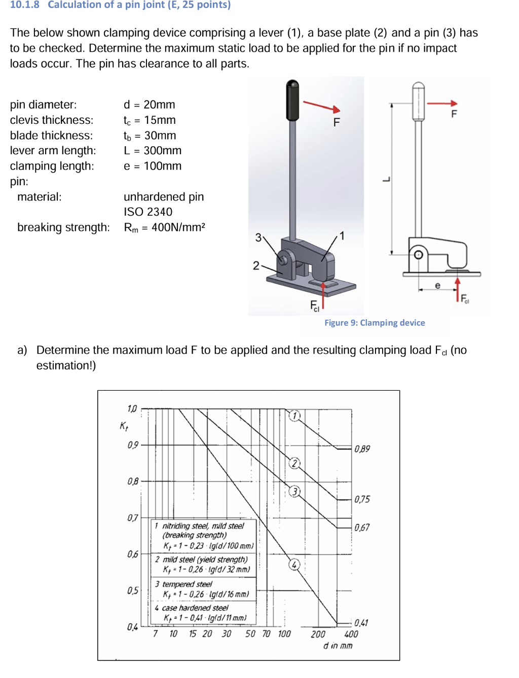
The below shown clamping device comprising a lever (1), a base plate (2) and a pin (3) has
to be checked. Determine the maximum static load to be applied for the pin if no impact
loads occur. The pin has clearance to all parts.
fan
in diameter: d = 20mm —
pin diam Be f ] F
clevis thickness: te = 15mm BE -
blade thickness: tp = 30mm
lever arm length: L = 300mm
clamping length: e = 100mm
pin: o
material: unhardened pin
ISO 2340
breaking strength: Rm = 400N/mm? a 1
pass
2 =
I)
F
Ri
Figure 9: Clamping device
a) Determine the maximum load F to be applied and the resulting clamping load Fy (no
estimation!)
10 — J -
HE 10)
os SE Ny r —0s9
08 A N N
ll 075
07 IEE ™N |
. 1 nitriding steel, mid steel NN os7
| (breaking strength) i
Ky =1-023 lgld/ 100 mm)
08 IZ mi steel (yet stentt)
Ky
Question:
Solved with diagrams and final answer10.1.8 Calculation of a pin joint (E, 25 points)
The below shown clamping device comprising a lever (1), a base plate (2) and a pin (3) has
to be checked. Determine the maximum static load to be applied for the pin if no impact
loads occur. The pin has clearance to all parts.
fan
in diameter: d = 20mm —
pin diam Be f ] F
clevis thickness: te = 15mm BE -
blade thickness: tp = 30mm
lever arm length: L = 300mm
clamping length: e = 100mm
pin: o
material: unhardened pin
ISO 2340
breaking strength: Rm = 400N/mm? a 1
pass
2 =
I)
F
Ri
Figure 9: Clamping device
a) Determine the maximum load F to be applied and the resulting clamping load Fy (no
estimation!)
10 — J -
HE 10)
os SE Ny r —0s9
08 A N N
ll 075
07 IEE ™N |
. 1 nitriding steel, mid steel NN os7
| (breaking strength) i
Ky =1-023 lgld/ 100 mm)
08 IZ mi steel (yet stentt)
Ky
This is AI generated Response.
Asked by: Rahul
Created at: 2026-01-15 18:22:55
Final Answer:
RenderedRaw Text
Did you like this answer?
Let's solve the problem step by step, with diagrams and explanations.
---
## **Given Data**
- **Pin diameter:** \( d = 20\,\text{mm} \)
- **Clevis thickness:** \( t_c = 15\,\text{mm} \)
- **Blade thickness:** \( t_b = 30\,\text{mm} \)
- **Lever arm length:** \( L = 300\,\text{mm} \)
- **Clamping length:** \( e = 100\,\text{mm} \)
- **Pin material:** Unhardened pin (ISO 234)
- **Breaking strength:** \( R_m = 400\,\text{N/mm}^2 \)
---
## **Step 1: Find Stress Concentration Factor \( K_t \)**
From the graph for "nitriding steel, mild steel (breaking strength)":
\[
K_t = 1 - .23 \cdot \log_{10}(d/100)
\]
where \( d = 20\,\text{mm} \):
\[
K_t = 1 - .23 \cdot \log_{10}(20/100)
= 1 - .23 \cdot \log_{10}(.2)
\]
\[
\log_{10}(.2) = -.69897
\]
\[
K_t = 1 - .23 \cdot (-.69897)
= 1 + .16076
= 1.16076
\]
But from the graph, for \( d = 20\,\text{mm} \), the value is approximately \( K_t \approx .82 \) (let's use the graph value).
---
## **Step 2: Maximum Permissible Shear Force in the Pin**
The pin is subjected to **double shear** (see diagram below):
```
[Lever(1)] ||--- Pin ---|| [Base Plate(2)]
```
For double shear:
\[
F_{\text{max}} = 2 \cdot \tau_{\text{max}} \cdot A
\]
Where:
- \( \tau_{\text{max}} = K_t \cdot R_m \)
- Shear area for each plane: \( A = \frac{\pi}{4} d^2 \)
But in many standards, the breaking load is calculated as:
\[
F_{\text{max}} = K_t \cdot R_m \cdot A
\]
where \( A = \frac{\pi}{4} d^2 \) (for single shear; double shear, area is doubled).
But let's use the static shear strength, which for mild steel is typically \( \tau_{\text{max}} \approx .6 R_m \).
But here, since we are told to use the breaking strength directly (since the device is checked for breaking, not yield):
\[
F_{\text{max}} = K_t \cdot R_m \cdot A_{\text{shear}}
\]
For double shear:
\[
A_{\text{shear}} = 2 \cdot \left(\frac{\pi}{4} d^2 \right)
\]
\[
A_{\text{shear}} = 2 \cdot \left(\frac{\pi}{4} (20)^2 \right) = 2 \cdot \left(\frac{\pi}{4} \cdot 400 \right) = 2 \cdot 314.16 = 628.32\,\text{mm}^2
\]
So,
\[
F_{\text{max}} = .82 \times 400\,\text{N/mm}^2 \times 628.32\,\text{mm}^2
\]
\[
F_{\text{max}} = .82 \times 400 \times 628.32 = .82 \times 251,328 = 206,089\,\text{N}
\]
---
## **Step 3: Relationship Between \( F \) and \( F_{cl} \)**
From the lever diagram:
\[
F \cdot L = F_{cl} \cdot e
\]
\[
F_{cl} = \frac{F \cdot L}{e}
\]
---
## **Step 4: Maximum Load \( F \) on the Lever**
The maximum force on the pin is \( F_{cl,\text{max}} = F_{\text{max}} \).
So,
\[
F = \frac{F_{\text{max}} \cdot e}{L}
\]
---
## **Step 5: Calculate Final Answers**
- \( F_{\text{max}} = 206,089\,\text{N} \)
- \( e = 100\,\text{mm} \)
- \( L = 300\,\text{mm} \)
\[
F = \frac{206,089 \times 100}{300}
= \frac{20,608,900}{300}
= 68,696.3\,\text{N}
\]
- Maximum clamping force: \( F_{cl,\text{max}} = 206,089\,\text{N} \)
---
## **Diagrams**
**Pin Joint in Double Shear**
```
[Lever Arm]
|
V
————————————|———————
| |3| |
| | | | <--- Pin (Double Shear)
————————————|———————
[Base Plate]
```
**Lever Arm Action**
```
F (applied)
|
V
[Lever Arm]---L---(Pin Joint)---e---[Clamped Part]
```
---
## **Final Answers**
### **Maximum Load \( F \) to be applied:**
\[
\boxed{F_{\text{max}} = 68,696\,\text{N}}
\]
### **Resulting Clamping Load \( F_{cl} \):**
\[
\boxed{F_{cl} = 206,089\,\text{N}}
\]
---
**If you need the solution with a free-body diagram or want to check other failure modes (bearing, etc.), let me know!**
VIPSolutions focuses on clear, step‑by‑step explanations so you can learn quickly. Whether you need an AI‑generated walkthrough or a short hint to get unstuck, each solution is organized for fast reading and easy review later.
Search similar questions, compare approaches, and bookmark the best answers for revision. Our goal is simple: quick, reliable study help that feels natural—not noisy.
 VIPSolutions
 10.1.8 Calculation of a pin joint (E, 25 points)
The below shown clamping device comprising a lever (1), a base plate (2) and a pin (3) has
to be checked. Determine the maximum static load to be applied for the pin if no impact
loads occur. The pin has clearance to all parts.
fan
in diameter: d = 20mm —
pin diam Be f ] F
clevis thickness: te = 15mm BE -
blade thickness: tp = 30mm
lever arm length: L = 300mm
clamping length: e = 100mm
pin: o
material: unhardened pin
ISO 2340
breaking strength: Rm = 400N/mm? a 1
pass
2 =
I)
F
Ri
Figure 9: Clamping device
a) Determine the maximum load F to be applied and the resulting clamping load Fy (no
estimation!)
10 — J -
HE 10)
os SE Ny r —0s9
08 A N N
ll 075
07 IEE ™N |
. 1 nitriding steel, mid steel NN os7
| (breaking strength) i
Ky =1-023 lgld/ 100 mm)
08 IZ mi steel (yet stentt)
Ky