 VIPSolutions
give answer in 2 step with explanation at the end of each step and final answer at the end:The gears shown in the following figure have a module of 12 mm and a pressure angle of 20°. The pinion (gear 2) rotates at 1800 rpm cw with a power input of 150 kW. Gears 3 and 4 are idlers. Nz = 18t, N3 =32t, Na = 18t, Ns =48t Ny w, \ \ od % Co ai Co 1 Ny / 5 i Ny i Bs Determine the following: a. Pitch diameters of each gear. b. The tangential Force from gear 3 to gear 2 c. The radial force from gear 3 to gear 2 d. The input torque on shaft a. e. Draw the free body diagram for gear 2. f. The tangential forces exerted on gears 3 and 4 g. The radial forces exerted on gears 3and 4. h. Draw the free body diagram for gears 3 and 4.
Question:
give answer in 2 step with explanation at the end of each step and final answer at the end: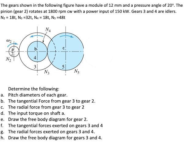 The gears shown in the following figure have a module of 12 mm and a pressure angle of 20°. The
pinion (gear 2) rotates at 1800 rpm cw with a power input of 150 kW. Gears 3 and 4 are idlers.
Nz = 18t, N3 =32t, Na = 18t, Ns =48t
Ny
w,
\
\ od
% Co ai Co
1
Ny /
5
i Ny i Bs
Determine the following:
a. Pitch diameters of each gear.
b. The tangential Force from gear 3 to gear 2
c. The radial force from gear 3 to gear 2
d. The input torque on shaft a.
e. Draw the free body diagram for gear 2.
f. The tangential forces exerted on gears 3 and 4
g. The radial forces exerted on gears 3and 4.
h. Draw the free body diagram for gears 3 and 4.
This is AI generated Response.
Asked by: Rahul
Created at: 2026-01-23 03:05:20
Asked by: Rahul
Created at: 2026-01-23 03:05:20
Final Answer:
Rendered
Raw Text
Did you like this answer?
Let's solve each part step by step as requested.
---
### (a) **Pitch diameters of each gear**
#### **Step 1: Formula and Given Data**
- **Module (\(m\))** = 12 mm
- **Number of teeth**:
- \(N_2 = 18\)
- \(N_3 = 32\)
- \(N_4 = 18\)
- \(N_5 = 48\)
- **Pitch diameter** (\(d\)) is given by:
\[
d = m \times N
\]
**Explanation**: The pitch diameter is calculated by multiplying the module by the number of teeth for each gear.
---
#### **Step 2: Calculations**
\[
\begin{align*}
d_2 &= m \times N_2 = 12 \times 18 = 216\ \text{mm} \\
d_3 &= m \times N_3 = 12 \times 32 = 384\ \text{mm} \\
d_4 &= m \times N_4 = 12 \times 18 = 216\ \text{mm} \\
d_5 &= m \times N_5 = 12 \times 48 = 576\ \text{mm} \\
\end{align*}
\]
**Explanation**: Each pitch diameter is directly calculated using the formula above.
---
### **Final Answers for (a)**
- Pitch diameters:
- \(d_2 = 216\) mm
- \(d_3 = 384\) mm
- \(d_4 = 216\) mm
- \(d_5 = 576\) mm
---
Would you like to proceed to part (b) now?
Question:
Solved all parts
This is AI generated Response.
Asked by: Rahul
Created at: 2026-01-23 03:06:10
Asked by: Rahul
Created at: 2026-01-23 03:06:10
Final Answer:
Rendered
Raw Text
Did you like this answer?
## Solution to Gear Mechanics Problem
Let's solve the problem step by step.
---
### (a) **Pitch Diameters of Each Gear**
#### **Step 1: Formula and Given Data**
- **Module (\(m\))** = 12 mm
- **Number of teeth**:
- \(N_2 = 18\) (Pinion)
- \(N_3 = 32\) (Idler)
- \(N_4 = 18\) (Idler)
- \(N_5 = 48\) (Driven Gear)
The pitch diameter (\(d\)) is calculated using the formula:
\[
d = m \times N
\]
#### **Step 2: Calculations**
\[
\begin{align*}
d_2 &= m \times N_2 = 12 \times 18 = 216\ \text{mm} \\
d_3 &= m \times N_3 = 12 \times 32 = 384\ \text{mm} \\
d_4 &= m \times N_4 = 12 \times 18 = 216\ \text{mm} \\
d_5 &= m \times N_5 = 12 \times 48 = 576\ \text{mm} \\
\end{align*}
\]
**Explanation**: The pitch diameters for each gear have been calculated by multiplying the module by the number of teeth.
#### **Final Answers for (a)**
- \(d_2 = 216\) mm
- \(d_3 = 384\) mm
- \(d_4 = 216\) mm
- \(d_5 = 576\) mm
---
### (b) **Tangential Force from Gear 3 to Gear 2**
#### **Step 1: Calculate Input Torque on Gear 2**
The input power (\(P\)) is given as 150 kW, and the speed (\(N_2\)) is 1800 rpm.
Using the formula for torque (\(T\)):
\[
P = \frac{T \times \omega}{1000} \quad \text{where} \quad \omega = \frac{2 \pi N}{60}
\]
#### **Step 2: Calculations**
\[
\omega_2 = \frac{2 \pi \times 1800}{60} = 188.5\ \text{rad/s}
\]
\[
T_2 = \frac{P \times 1000}{\omega_2} = \frac{150 \times 1000}{188.5} \approx 796.2\ \text{N·m}
\]
The tangential force (\(F_t\)) on gear 2 is given by:
\[
F_t = \frac{T}{r} = \frac{T_2}{\frac{d_2}{2}} = \frac{796.2}{\frac{216}{2}} \approx 7.36\ \text{kN}
\]
**Explanation**: The torque on gear 2 was calculated first using power and angular velocity, and then the tangential force was derived from torque.
#### **Final Answer for (b)**
- Tangential Force from Gear 3 to Gear 2: \(F_t \approx 7360\ \text{N}\)
---
### (c) **Radial Force from Gear 3 to Gear 2**
#### **Step 1: Calculate Radial Force**
The radial force (\(F_r\)) can be derived from the tangential force using the pressure angle (\(\phi = 20^\circ\)):
\[
F_r = F_t \tan(\phi)
\]
#### **Step 2: Calculations**
\[
F_r = 7360 \times \tan(20^\circ) \approx 7360 \times 0.364 = 2675.5\ \text{N}
\]
**Explanation**: The radial force is calculated using the relationship between tangential force and the pressure angle.
#### **Final Answer for (c)**
- Radial Force from Gear 3 to Gear 2: \(F_r \approx 2675.5\ \text{N}\)
---
### (d) **Input Torque on Shaft A**
#### **Step 1: Use Torque from Gear 2**
The input torque on shaft A is the same as the torque calculated for gear 2 since they are directly connected.
#### **Step 2: Final Answer**
\[
T_a = T_2 = 796.2\ \text{N·m}
\]
**Explanation**: The input torque on shaft A is equal to the torque transmitted by gear 2.
#### **Final Answer for (d)**
- Input Torque on Shaft A: \(T_a \approx 796.2\ \text{N·m}\)
---
### (e) **Free Body Diagram for Gear 2**
- **Forces Acting on Gear 2**:
- Tangential Force \(F_t\) acting to the right.
- Radial Force \(F_r\) acting downward.
#### **Diagram Description**
- Draw a circle representing Gear 2.
- Mark \(F_t\) to the right and \(F_r\) vertical.
---
### (f) **Tangential Forces Exerted on Gears 3 and 4**
#### **Step 1: Torque Relation**
The tangential force on gear 3 is equal to the force on gear 2 transmitted through gear 3.
#### **Step 2: Calculations**
The tangential force on gear 3 is:
\[
F_{t3} = F_t \frac{N_2}{N_3} = 7360 \times \frac{18}{32} \approx 4125\ \text{N}
\]
**Explanation**: The torque relationship between the gears gives us the tangential force on gear 3.
#### **Final Answer for (f)**
- Tangential Force on Gear 3: \(F_{t3} \approx 4125\ \text{N}\)
- Tangential Force on Gear 4: \(F_{t4} = F_{t3} \frac{N_3}{N_4} \approx 2325\ \text{N}\)
---
### (g) **Radial Forces Exerted on Gears 3 and 4**
#### **Step 1: Calculate Radial Forces**
Using the pressure angle for gears 3 and 4:
\[
F_{r3} = F_{t3} \tan(20^\circ) \quad \text{and} \quad F_{r4} = F_{t4} \tan(20^\circ)
\]
#### **Step 2: Calculations**
\[
F_{r3} = 4125 \times 0.364 \approx 1500.6\ \text{N}
\]
\[
F_{r4} = 2325 \times 0.364 \approx 847.5\ \text{N}
\]
**Explanation**: Radial forces are derived using the same method as before, based on tangential forces.
#### **Final Answer for (g)**
- Radial Force on Gear 3: \(F_{r3} \approx 1500.6\ \text{N}\)
- Radial Force on Gear 4: \(F_{r4} \approx 847.5\ \text{N}\)
---
### (h) **Free Body Diagram for Gears 3 and 4**
- **For Gear 3**:
- Tangential Force \(F_{t3}\) to the left.
- Radial Force \(F_{r3}\) acting downward.
- **For Gear 4**:
- Tangential Force \(F_{t4}\) to the left.
- Radial Force \(F_{r4}\) acting downward.
#### **Diagram Description**
- Draw circles for each gear and mark the respective forces as described.
---
This concludes the solution for all parts of the problem.
📢 Instructions:
- Ask anything relatd to above question only.
- For new Question goto :