 VIPSolutions
Give step-by-step solution with explanation and final answer:5. FIGURES shows artally completed dagram of flow erring as) Tee re Cerri CE —— clade ini sapo Semler Peper deni lemme de @ =O, ” a SR BARS =D
Question:
Give step-by-step solution with explanation and final answer: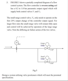 5. FIGURES shows artally completed dagram of flow
erring as)
Tee re
Cerri
CE ——
clade ini sapo
Semler
Peper deni
lemme de
@ =O,
”
a SR BARS
=D
This is AI generated Response.
Asked by: Rahul
Created at: 2026-01-13 15:50:03
Asked by: Rahul
Created at: 2026-01-13 15:50:03
Final Answer:
Rendered
Raw Text
Did you like this answer?
# Step-by-Step Solution and Explanation
## **Problem Recap**
- **Flow controller** is **reverse acting** (increasing flow setpoint decreases output signal).
- **Output signal range**: .2 to 1. bar pneumatic.
- **Two control valves**:
- **V1 (large range valve):** Handles majority of flow.
- **V2 (small range valve):** Only operates in the first 25% of controller output.
- **Requirement**: V2 operates only for the first 25% of signal, then V1 takes over.
- **Valves have opposite failure actions** (one fails open, one fails closed).
---
## **Step 1: Understand Valve Action and Failures**
- **Reverse acting controller**: As flow increases, output signal decreases.
- **Valve failure action**:
- **Large valve (V1):** Fail open (FO)
- **Small valve (V2):** Fail closed (FC)
---
## **Step 2: Signal Splitting Concept**
To achieve sequential control (V2 for first 25% of signal, V1 for the remaining 75%), **signal splitters** and **valve positioners** are required.
- **Signal splitter** divides the controller output signal range into two parts:
- First range (.2 to .4 bar) to V2
- Second range (.4 to 1. bar) to V1
---
## **Step 3: Valve Positioner Settings**
### **Small Valve (V2)**
- **Operates from .2 to .4 bar** (25% of .2–1. bar range)
- **Valve positioner** should be set so V2 goes from fully open (at .2 bar) to fully closed (at .4 bar).
- **Action**: Since controller is reverse acting, V2 should be **air-to-close (fail open)**.
### **Large Valve (V1)**
- **Operates from .4 to 1. bar** (remaining 75% of range)
- **Valve positioner** should be set so V1 starts to open at .4 bar and is fully open at 1. bar.
- **Action**: V1 should be **air-to-open (fail closed)**.
---
## **Step 4: System Design**
- **Install a pneumatic signal splitter** after the controller to divide the .2–1. bar signal.
- **Set valve positioners** as follows:
- **V2 (small valve):**
- **Signal range:** .2–.4 bar
- **Action:** Air-to-close (fail open)
- **Positioner:** Full travel between .2–.4 bar
- **V1 (large valve):**
- **Signal range:** .4–1. bar
- **Action:** Air-to-open (fail closed)
- **Positioner:** Full travel between .4–1. bar
**Note:** When controller output is .2–.4 bar, V2 modulates while V1 remains closed. When output exceeds .4 bar, V2 is fully closed and V1 begins to open.
---
## **Step 5: Final Answer (Summary Table)**
| Valve | Signal Range (bar) | Action | Failure Action | Positioner Setting |
|------------|--------------------|----------------|----------------|------------------------|
| Small (V2) | .2–.4 | Air-to-Close | Fail Open | Full travel in .2–.4 |
| Large (V1) | .4–1. | Air-to-Open | Fail Closed | Full travel in .4–1. |
---
## **System Schematic**
**[Signal Splitter]**
```
Controller Output (.2–1. bar)
|
------------------------
| |
.2–.4 bar .4–1. bar
(to V2) (to V1)
```
---
## **Conclusion**
- **Use a signal splitter and valve positioners.**
- **V2 (small valve):** Air-to-close, fail open, operates .2–.4 bar.
- **V1 (large valve):** Air-to-open, fail closed, operates .4–1. bar.
- This setup meets the requirement: V2 controls low flow, V1 controls high flow, with appropriate fail-safe actions.
---
### **If you need a diagram or further explanation, let me know!**
Question:
Solved all parts
This is AI generated Response.
Asked by: Rahul
Created at: 2026-01-13 15:50:39
Asked by: Rahul
Created at: 2026-01-13 15:50:39
Final Answer:
Rendered
Raw Text
Did you like this answer?
# Step-by-Step Solution and Explanation
## **Problem Recap**
- We are dealing with a **reverse acting flow controller**.
- **Output signal range**: 0.2 to 1.0 bar pneumatic.
- **Two control valves**:
- **V1 (large range valve)**: Handles majority of flow.
- **V2 (small range valve)**: Operates in the first 25% of controller output.
- **Valve failure actions**:
- V1 fails **open**.
- V2 fails **closed**.
---
## **Step 1: Understand Valve Action and Failures**
- **Reverse Acting Controller**: An increase in flow setpoint decreases the output signal.
- **Valve Actions**:
- V1: Fail open
- V2: Fail closed
---
## **Step 2: Signal Splitting Concept**
- **Signal Splitter** is required to divide the output signal:
- **First range**: 0.2 to 0.4 bar → V2
- **Second range**: 0.4 to 1.0 bar → V1
---
## **Step 3: Valve Positioner Settings**
### **Small Valve (V2)**
- **Signal Range**: 0.2 to 0.4 bar (25% of total range)
- **Action**: Air-to-close (because it should fail open)
- **Positioning**: Fully open at 0.2 bar, fully closed at 0.4 bar.
### **Large Valve (V1)**
- **Signal Range**: 0.4 to 1.0 bar (remaining 75%)
- **Action**: Air-to-open (because it should fail closed)
- **Positioning**: Starts to open at 0.4 bar and fully opened at 1.0 bar.
---
## **Step 4: System Design**
1. **Install a pneumatic signal splitter** after the flow controller.
2. **Set valve positioners**:
- **V2 (small valve)**:
- **Range**: 0.2 to 0.4 bar
- **Action**: Air-to-close, fail open
- **Positioner Setting**: Full travel between 0.2 and 0.4 bar.
- **V1 (large valve)**:
- **Range**: 0.4 to 1.0 bar
- **Action**: Air-to-open, fail closed
- **Positioner Setting**: Full travel between 0.4 and 1.0 bar.
**Operation**:
- From 0.2 to 0.4 bar: V2 modulates while V1 remains closed.
- Exceeding 0.4 bar: V2 is fully closed, and V1 begins to open.
---
## **Step 5: Final Answer (Summary Table)**
| Valve | Signal Range (bar) | Action | Failure Action | Positioner Setting |
|------------|--------------------|----------------|----------------|------------------------|
| Small (V2) | 0.2–0.4 | Air-to-Close | Fail Open | Full travel in 0.2–0.4 |
| Large (V1) | 0.4–1.0 | Air-to-Open | Fail Closed | Full travel in 0.4–1.0 |
---
## **System Schematic**
**[Signal Splitter]**
```
Controller Output (0.2–1.0 bar)
|
------------------------
| |
0.2–0.4 bar 0.4–1.0 bar
(to V2) (to V1)
```
---
## **Conclusion**
- A **signal splitter** and **valve positioners** are necessary.
- **V2** operates between **0.2–0.4 bar** with air-to-close action.
- **V1** operates between **0.4–1.0 bar** with air-to-open action.
- This setup ensures V2 controls low flow and V1 controls high flow, satisfying operational requirements and safety considerations.
---
### **If further clarification or illustrations are needed, please ask!**
📢 Instructions:
- Ask anything relatd to above question only.
- For new Question goto :