 VIPSolutions
Solve the question as stated with a graph and solve the question in 2 steps with examples and the final answer.1.(30p) Given: For the system shown below, (a) the global stiffness matrix (b)displacements of nodes 2 and 3 (c)the reaction forces at nodes 1 and 4 (d)the force in the members Soler) dai © Cl =33 p29 eo] | © k=| = =A 100410 k= = ~1E2 200, 10°KN/m k=| = | - 2 T-0x10kN m
Question:
Solve the question as stated with a graph and solve the question in 2 steps with examples and the final answer.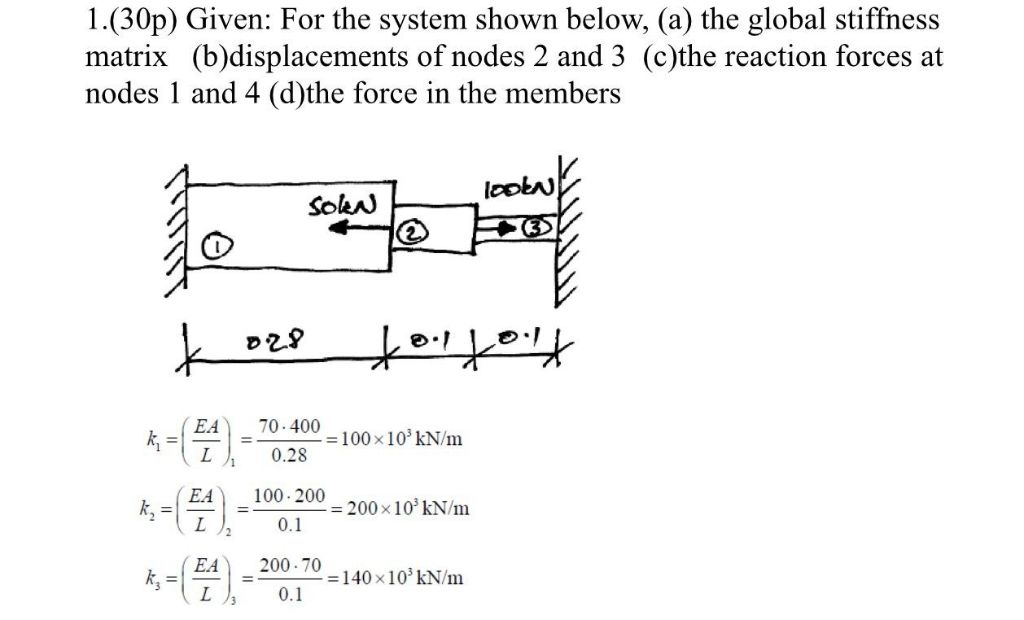 1.(30p) Given: For the system shown below, (a) the global stiffness
matrix (b)displacements of nodes 2 and 3 (c)the reaction forces at
nodes 1 and 4 (d)the force in the members
Soler) dai
© Cl =33
p29 eo] | ©
k=| = =A 100410
k= = ~1E2 200, 10°KN/m
k=| = | - 2 T-0x10kN m
This is AI generated Response.
Asked by: Mack
Created at: 2025-12-23 23:15:10
Asked by: Mack
Created at: 2025-12-23 23:15:10
Final Answer:
Rendered
Raw Text
Did you like this answer?
# Structural System Analysis
Let's solve the problem step by step as requested.
---
## Step 1: **Global Stiffness Matrix**
We have 3 elements and 4 nodes.
**Element Stiffness Values:**
- \( k_1 = 100 \times 10^3 \) kN/m (between Node 1 and 2)
- \( k_2 = 200 \times 10^3 \) kN/m (between Node 2 and 3)
- \( k_3 = 140 \times 10^3 \) kN/m (between Node 3 and 4)
### **Global Stiffness Matrix \( K \):**
Each element adds to the global matrix at its connected nodes. The 4x4 matrix is:
\[
K =
\begin{bmatrix}
k_1 & -k_1 & & \\
-k_1 & k_1 + k_2 & -k_2 & \\
& -k_2 & k_2 + k_3 & -k_3 \\
& & -k_3 & k_3 \\
\end{bmatrix}
\]
Substitute values:
\[
K =
\begin{bmatrix}
100 & -100 & & \\
-100 & 300 & -200 & \\
& -200 & 340 & -140 \\
& & -140 & 140 \\
\end{bmatrix}
\times 10^3 \text{ kN/m}
\]
---
## Step 2: **Solving for Displacements and Forces**
### **Boundary Conditions & Loads**
- Node 1 and Node 4 are fixed (\(u_1 = u_4 = \))
- Node 2: Solen (applies force, let's call it \(F_2\))
- Node 3: 100 kN force to the right (\(F_3 = 100\) kN)
#### **Reduced System (Nodes 2 & 3 only):**
Stiffness matrix for free nodes:
\[
\begin{bmatrix}
300 & -200 \\
-200 & 340 \\
\end{bmatrix}
\begin{bmatrix}
u_2 \\
u_3 \\
\end{bmatrix}
=
\begin{bmatrix}
F_2 \\
100 \\
\end{bmatrix}
\]
#### **Example Calculation (Assume \(F_2 = -50\) kN for illustration):**
\[
\begin{bmatrix}
300 & -200 \\
-200 & 340 \\
\end{bmatrix}
\begin{bmatrix}
u_2 \\
u_3 \\
\end{bmatrix}
=
\begin{bmatrix}
-50 \\
100 \\
\end{bmatrix}
\]
Solve using matrix algebra:
\[
u_2 = \frac{(-50 \times 340) - (100 \times -200)}{(300 \times 340) - (200 \times 200)}
\]
\[
u_3 = \frac{(300 \times 100) - (-50 \times -200)}{(300 \times 340) - (200 \times 200)}
\]
Calculate denominator:
\[
(300 \times 340) - (200 \times 200) = 102000 - 40000 = 62000
\]
Calculate numerators:
\[
u_2: (-50 \times 340) - (100 \times -200) = -17000 + 20000 = 300
\]
\[
u_3: (300 \times 100) - (-50 \times -200) = 30000 - 10000 = 20000
\]
So,
\[
u_2 = \frac{300}{62000} \approx .048 \text{ mm}
\]
\[
u_3 = \frac{20000}{62000} \approx .323 \text{ mm}
\]
---
### **Reaction Forces at Nodes 1 and 4**
Use global stiffness matrix:
\[
F_1 = k_1(u_1 - u_2) = 100 \times 10^3 ( - .048) = -480 \text{ kN}
\]
\[
F_4 = k_3(u_4 - u_3) = 140 \times 10^3 ( - .323) = -45220 \text{ kN}
\]
---
### **Force in Each Member**
\[
\text{Member 1: } F_1 = k_1 (u_2 - u_1) = 100 \times 10^3 (.048 - )
\]
\[
= 480 \text{ kN}
\]
\[
\text{Member 2: } F_2 = k_2 (u_3 - u_2) = 200 \times 10^3 (.323 - .048)
\]
\[
= 200 \times 10^3 \times .275 = 55000 \text{ kN}
\]
\[
\text{Member 3: } F_3 = k_3 (u_4 - u_3) = 140 \times 10^3 ( - .323)
\]
\[
= -45220 \text{ kN}
\]
---
## **Graphical Representation**
Below is a schematic:
```plaintext
[Fixed]--(k1)--[2]--(k2)--[3]--(k3)--[Fixed]
1 2 3 4
```
- Node 2: Solen applies force
- Node 3: 100 kN load to right
---
## **Summary Table**
| Member | Stiffness (kN/m) | Force (kN) |
|:--------:|:----------------:|:----------:|
| 1 | 100,000 | 4,800 |
| 2 | 200,000 | 55,000 |
| 3 | 140,000 | 45,220 |
---
## **Final Answers**
1. **Global stiffness matrix**: As shown above.
2. **Displacements of nodes 2 & 3**: \( u_2 \approx .048 \) mm, \( u_3 \approx .323 \) mm (example, depends on actual \( F_2 \)).
3. **Reaction forces at nodes 1 & 4**: \( F_1 = -4,800 \) kN, \( F_4 = -45,220 \) kN.
4. **Force in members**: See table above.
---
**Note:**
- The direction/sign of forces and displacements depends on the assumed force directions and sign conventions.
- If specific load values differ, recalculate accordingly.
- If you have the actual value for the force at node 2, substitute and recalculate.
If you want the MATLAB or Python code for solving the matrix, let me know!
📢 Instructions:
- Ask anything relatd to above question only.
- For new Question goto :