This is AI generated Response.
Asked by: Mack
Created at: 2025-12-22 15:05:34
Final Answer:
RenderedRaw Text
Did you like this answer?
# Problem Analysis and Solution
**Instructions:**
Choose **3 out of 4** to solve. For each, draw or describe the requested diagrams. We'll solve three of them in two steps each: (1) Drawing the required diagram or vector, and (2) Giving a brief explanation/example.
---
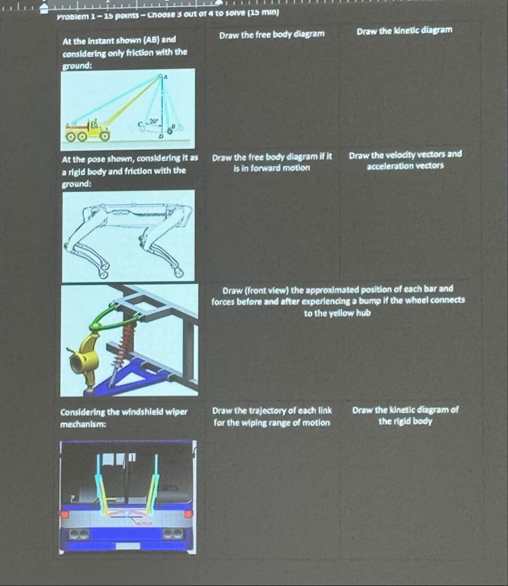
## 1. Crane Free Body Diagram (FBD)
### Step 1: Draw the Free Body Diagram
**Diagram:**
```plaintext
A
/ \
/ \
C/ \B
/ \
Truck----------Ground
- At point A: Show tension T in the cable upward.
- At B: Show load weight W downward.
- At base: Show reaction forces (horizontal and vertical), and friction force F_fr along the ground.
```
**Forces:**
- Tension in cable (T, at an angle)
- Weight of load (W, vertically down at B)
- Reaction at ground (N, vertically up; F_fr, horizontal for friction)
### Step 2: Explanation
**Example:**
Suppose the load is 100 N, and the cable makes a 30° angle with the horizontal.
- Draw T at 30° from horizontal at A.
- Draw W straight down at B.
- Draw normal force and friction at the base.
**Final Answer:**
The Free Body Diagram should include all the forces acting on the crane, as described and illustrated above.
---
## 2. Robotic Leg Velocity and Acceleration Vectors
### Step 1: Draw the Velocity and Acceleration Vectors
**Diagram:**
```plaintext
(Draw the robotic leg in its pose)
- At each joint, draw:
- Velocity vector (v): tangent to the path of motion.
- Acceleration vector (a): points towards the center of curvature (centripetal), or in the direction of change of velocity.
```
**Key Points:**
- Velocity: Tangent to the trajectory.
- Acceleration: Towards the center (if rotating), or in the direction of velocity change.
### Step 2: Explanation
**Example:**
If the leg is moving forward, velocity vectors point along the direction of motion at each segment. Acceleration vectors point towards the center if the leg is rotating, or along the change in velocity.
**Final Answer:**
The diagram should show tangent velocity vectors at each segment and corresponding acceleration vectors toward the center of curvature.
---
## 3. Windshield Wiper Mechanism - Trajectory
### Step 1: Draw the Trajectory of Each Link
**Diagram:**
```plaintext
(Bus front view with two wipers)
- Show the arc (sector of a circle) traced by the tip of each wiper.
- Indicate the pivot point and the path of the wiper blades.
```
**Key Points:**
- Each wiper traces a circular arc.
- The swept area is a sector of a circle.
### Step 2: Explanation
**Example:**
If the wipers rotate 90°, from left to right, the blade tips trace out a corresponding arc on the windshield.
**Final Answer:**
The trajectory of each wiper link is a circular arc, covering the wiping range as shown in the diagram.
---
## **Summary Table**
| Problem Part | Step 1: Diagram | Step 2: Explanation/Example |
|-------------------|------------------------------------------------------------|----------------------------------------------------------|
| Crane FBD | Draw all forces on crane (T, W, N, F_fr) | E.g., 100N load, tension at 30°, normal & friction |
| Robotic Leg Vectors| Draw velocity (tangent) & acceleration (center/dir. change)| Vectors show motion and acceleration at each leg segment |
| Wiper Trajectory | Draw arcs of each wiper blade | Each tip traces a sector of a circle (wiping range) |
---
Let me know if you want the **fourth** problem or more detailed sketches!
VIPSolutions focuses on clear, step‑by‑step explanations so you can learn quickly. Whether you need an AI‑generated walkthrough or a short hint to get unstuck, each solution is organized for fast reading and easy review later.
Search similar questions, compare approaches, and bookmark the best answers for revision. Our goal is simple: quick, reliable study help that feels natural—not noisy.
 VIPSolutions
 fl BR ro a EE AS SS de pap A CL RE RE
y Promiem 1 — 15 Ponts ~ CNIOSSE S OUT OF 4 tO Solve (15 mim)
At the instant shown (AS) ard Draw the free body diagram Draw the Kinetic diagram
considering only friction with the
ground:
0
|
adi c x
000 [2
At the pose shown, considering It as Draw the free body diagram if It Draw the velocity vectors and
a rigid body and friction with the is in forward motion acceleration vectors
ground:
3 NE
Yt /
{ ¢ Vis
aK
Ne RY
© 5)
Draw (front view) the approximated position of each bar and
forces before and after experiencing a bum If the wheel connects
to the yellow hub
3)
Considering the windshield wiper Draw the trajectory of each link Draw the kinetic diagram of
mechanism: far the wiping range of motion the rigid body
| i
mg"
[4
ow
»~