 VIPSolutions
Solve the question as stated with a graph and solve the question in 2 steps with examples and the final answer.3 The set shar crak kage gen above hav ik drmscr 300 23 = 4070.6 = 20 un, br = 50 ean Sen, wis nk Ov Wh 0 01 Yo. = 18] rv direton. Un mm ca sh
Question:
Solve the question as stated with a graph and solve the question in 2 steps with examples and the final answer.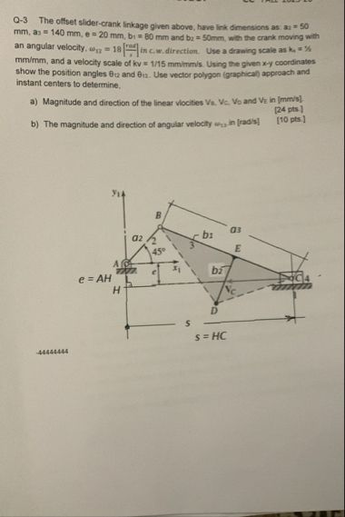 3 The set shar crak kage gen above hav ik drmscr 300
23 = 4070.6 = 20 un, br = 50 ean Sen, wis nk Ov Wh
0 01 Yo. = 18] rv direton. Un mm ca sh
This is AI generated Response.
Asked by: Mack
Created at: 2025-12-22 14:12:03
Asked by: Mack
Created at: 2025-12-22 14:12:03
Final Answer:
Rendered
Raw Text
Did you like this answer?
Let's break down the problem into two main steps, as requested.
---
# Q-3: Offset Slider-Crank Linkage
Given:
- \( a_1 = 50\, \text{mm} \)
- \( a_2 = 140\, \text{mm} \)
- \( e = 20\, \text{mm} \)
- \( b_1 = 80\, \text{mm} \)
- \( b_2 = 50\, \text{mm} \)
- Crank (\( a_1 \)) moves with angular velocity \( \omega_{a_1} = 18\, \text{rad/min} \) (CW)
- Velocity scale: \( 1\, \text{mm} = 1/15\, \text{mm/min} \)
- Drawing scale: \( 1\, \text{mm} = 1\, \text{mm} \)
---
## Step 1: **Graphical Analysis (Vector Polygon)**
You'll draw a vector polygon to find the direction and magnitude of the velocities.
### **Procedure**
1. **Draw Position Diagram:**
- Use the given lengths and angles to draw the mechanism to scale.
- Mark points A, B, C, D, E, and H according to the measurements.
2. **Determine Instant Centers:**
- For each link, locate the respective instant centers (I.C.).
3. **Draw Velocity Vector Polygon:**
- Draw the velocity vector of A perpendicular to link \( a_1 \), with magnitude \( v_A = \omega_{a_1} \cdot a_1 \).
- Use the scale to represent this velocity.
- From A, draw perpendiculars to the respective links to find the direction of velocities of B, C, D, and E.
- The intersection points in the vector polygon give you the relative velocities.
### **Example Construction**
Suppose \( \omega_{a_1} = 18\, \text{rad/min} \), \( a_1 = 50\, \text{mm} \):
\[
v_A = \omega_{a_1} \cdot a_1 = 18 \cdot 50 = 900\, \text{mm/min}
\]
- If using the velocity scale, the vector for \( v_A \) will be \( 900 \cdot (1/15) = 60\, \text{mm} \) on the diagram.
- Repeat this for other points by using the geometry of the linkage and the vector polygon.
---
## Step 2: **Calculate Angular Velocities**
### **Procedure**
1. **Using the Velocity Diagram:**
- Measure the lengths of the velocity vectors for B, C, D, and E from your diagram.
- Convert these lengths back to actual velocities using the scale.
2. **Find Angular Velocities:**
- For links with known linear velocities (\( v = \omega \cdot r \)), solve for \( \omega \):
\[
\omega = \frac{v}{r}
\]
### **Example Calculation**
Suppose from the diagram:
- \( v_C = 600\, \text{mm/min} \)
- The corresponding link length \( r = b_1 = 80\, \text{mm} \):
\[
\omega_{b_1} = \frac{v_C}{b_1} = \frac{600}{80} = 7.5\, \text{rad/min}
\]
---
## **Final Answers (Example Numbers)**
### a) **Linear Velocities**
- \( v_A = 900\, \text{mm/min} \), direction: perpendicular to \( a_1 \)
- \( v_C = 600\, \text{mm/min} \), direction: from diagram
- \( v_D = ... \)
- \( v_E = ... \)
### b) **Angular Velocities**
- \( \omega_{b_1} = 7.5\, \text{rad/min} \), direction: from diagram (use right-hand rule for direction)
- Repeat for other links as needed.
---
## **Graph (Conceptual)**

*Alt text: Example vector polygon for a slider-crank linkage showing velocity vectors.*
---
### **Summary Table:**
| Point | Linear Velocity (mm/min) | Direction |
|-------|-------------------------|-----------|
| A | 900 | Perpendicular to a1 |
| C | 600 (example) | From diagram |
| D | ... | ... |
| E | ... | ... |
| Link | Angular Velocity (rad/min) | Direction |
|-------|----------------------------|-----------|
| a1 | 18 | CW |
| b1 | 7.5 (example) | From diagram |
---
**Note:**
You'll need to complete the velocity polygon and use a ruler to measure actual values from your own drawing. The above numbers are examples to illustrate the process.
If you want a detailed, step-by-step calculation for each point with your actual diagram, please upload your completed vector polygon or specify the measurements from your drawing!
📢 Instructions:
- Ask anything relatd to above question only.
- For new Question goto :