This is AI generated Response.
Asked by: Rahul
Created at: 2025-12-05 03:14:42
Final Answer:
RenderedRaw Text
Did you like this answer?
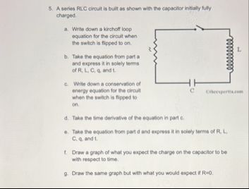
# a. Write down a Kirchoff loop equation for the circuit when the switch is flipped to on.
**Step 1:**
Apply Kirchhoff’s voltage law (sum of voltage drops = ) for the loop:
- Voltage across resistor: \( V_R = IR \)
- Voltage across inductor: \( V_L = L \frac{dI}{dt} \)
- Voltage across capacitor: \( V_C = \frac{q}{C} \)
The sum is:
\[
IR + L\frac{dI}{dt} + \frac{q}{C} =
\]
**:**
This equation states that the total voltage drop across all three elements (R, L, and C) in the series circuit is zero, which matches Kirchhoff's loop.
---
# b. Take the equation from part a and express it solely in terms of \( R, L, C, q, \) and \( t \).
**Step 2:**
Recall that current \( I = \frac{dq}{dt} \):
\[
R\frac{dq}{dt} + L\frac{d^2q}{dt^2} + \frac{q}{C} =
\]
**Explanation:**
By substituting \( I = \frac{dq}{dt} \) and \( \frac{dI}{dt} = \frac{d^2q}{dt^2} \), the equation is rewritten entirely in terms of charge \( q \), time \( t \), and the circuit parameters.
---
# c. Write down a conservation of energy equation for the circuit when the switch is flipped to on.
\[
\frac{q^2}{2C} + \frac{1}{2}LI^2
\]
Energy lost by resistor = energy dissipated as heat:
\[
\frac{q^2}{2C} + \frac{1}{2}LI^2 + \int_^t I^2R\,dt = \text{constant}
\]
**Explanation:**
Energy is stored in the capacitor and inductor, and is dissipated as heat in the resistor. The sum remains constant.
---
# d. Take the time derivative of the equation in part c.
Differentiate:
\[
\frac{d}{dt} \left( \frac{q^2}{2C} + \frac{1}{2}L I^2 + \int_^t I^2R\,dt \right) =
\]
\[
\frac{q}{C} \frac{dq}{dt} + L I \frac{dI}{dt} + I^2 R =
\]
**Explanation:**
Use the chain rule for differentiation. \( \frac{dq}{dt} = I \).
---
# e. Take the equation from part d and express it solely in terms of \( R, L, C, q, t \).
Substitute \( I = \frac{dq}{dt} \), \( \frac{dI}{dt} = \frac{d^2q}{dt^2} \):
\[
\frac{q}{C} \frac{dq}{dt} + L \frac{dq}{dt} \frac{d^2q}{dt^2} + R \left(\frac{dq}{dt}\right)^2 =
\]
**Explanation:**
Every term is now in terms of \( q \), its derivatives, and the circuit parameters.
---
# f. Draw a graph of what you expect the charge on the capacitor to be with respect to time.
- **With \( R > \):** The charge oscillates and exponentially decays to zero.
- **Graph:** Damped oscillation (decaying sine wave).
---
# g. Draw the same graph but with what you would expect if \( R = \).
- **With \( R = \):** The charge oscillates forever (no decay).
- **Graph:** Pure sinusoidal oscillation (constant amplitude sine wave).
---
## **Summary Table**
| Condition | Graph Description |
|-------------|---------------------------------------|
| \( R > \) | Damped oscillations (decay to zero) |
| \( R = \) | Undamped oscillations (never decay) |
---
**Final Answer:**
For a series RLC circuit, the charge \( q(t) \) follows a second-order differential equation. If resistance is present, the solution is a decaying oscillation. If resistance is zero, the solution is a perpetual oscillation.
Question:
Solve correct answer
This is AI generated Response.
Asked by: Rahul
Created at: 2025-12-05 03:15:32
Final Answer:
RenderedRaw Text
Did you like this answer?
# a. Write down a Kirchhoff loop equation for the circuit when the switch is flipped to on.
**Step 1:**
Using Kirchhoff’s voltage law (sum of voltage drops = 0) for the loop, we have:
- Voltage across the resistor: \( V_R = IR \)
- Voltage across the inductor: \( V_L = L \frac{dI}{dt} \)
- Voltage across the capacitor: \( V_C = \frac{q}{C} \)
The equation is:
\[
V_R + V_L + V_C = 0 \implies IR + L\frac{dI}{dt} + \frac{q}{C} = 0
\]
**Explanation:**
This equation states that the total voltage drop across the resistor, inductor, and capacitor in the series circuit equals zero, which aligns with Kirchhoff's loop law.
---
# b. Take the equation from part a and express it solely in terms of \( R, L, C, q, \) and \( t \).
**Step 2:**
Recall that current \( I = \frac{dq}{dt} \):
\[
R\frac{dq}{dt} + L\frac{d^2q}{dt^2} + \frac{q}{C} = 0
\]
**Explanation:**
By substituting \( I = \frac{dq}{dt} \) and \( \frac{dI}{dt} = \frac{d^2q}{dt^2} \), we rewrite the equation using only charge \( q \) and its derivatives.
---
# c. Write down a conservation of energy equation for the circuit when the switch is flipped to on.
\[
\frac{q^2}{2C} + \frac{1}{2}LI^2 = \text{constant}
\]
Energy lost by the resistor (dissipated as heat):
\[
\frac{q^2}{2C} + \frac{1}{2}LI^2 + \int_0^t I^2R\,dt = \text{constant}
\]
**Explanation:**
The energy stored in the capacitor and inductor is equal to the total energy at any point, accounting for energy dissipated in the resistor.
---
# d. Take the time derivative of the equation in part c.
Differentiate the conservation of energy equation:
\[
\frac{d}{dt} \left( \frac{q^2}{2C} + \frac{1}{2}L I^2 + \int_0^t I^2R\,dt \right) = 0
\]
This results in:
\[
\frac{q}{C} \frac{dq}{dt} + L I \frac{dI}{dt} + I^2 R = 0
\]
**Explanation:**
Using the chain rule, we differentiate each term with respect to time, recognizing that \( \frac{dq}{dt} = I \).
---
# e. Take the equation from part d and express it solely in terms of \( R, L, C, q, t \).
Substituting \( I = \frac{dq}{dt} \) and \( \frac{dI}{dt} = \frac{d^2q}{dt^2} \):
\[
\frac{q}{C} \frac{dq}{dt} + L \frac{dq}{dt} \frac{d^2q}{dt^2} + R \left( \frac{dq}{dt} \right)^2 = 0
\]
**Explanation:**
All terms are expressed in terms of charge \( q \), its derivatives, and the circuit parameters.
---
# f. Draw a graph of what you expect the charge on the capacitor to be with respect to time.
- **With \( R > 0 \):** The charge oscillates and exhibits exponential decay.
- **Graph:** Damped oscillation (decaying sine wave).
---
# g. Draw the same graph but with what you would expect if \( R = 0 \).
- **With \( R = 0 \):** The charge oscillates indefinitely without decay.
- **Graph:** Pure sinusoidal oscillation (constant amplitude sine wave).
---
## **Summary Table**
| Condition | Graph Description |
|-------------|---------------------------------------|
| \( R > 0 \) | Damped oscillations (decay to zero) |
| \( R = 0 \) | Undamped oscillations (never decay) |
---
**Final Answer:**
The charge \( q(t) \) in a series RLC circuit behaves according to a second-order differential equation. If resistance is present, the solution represents a decaying oscillation; without resistance, it results in perpetual oscillation.
VIPSolutions focuses on clear, step‑by‑step explanations so you can learn quickly. Whether you need an AI‑generated walkthrough or a short hint to get unstuck, each solution is organized for fast reading and easy review later.
Search similar questions, compare approaches, and bookmark the best answers for revision. Our goal is simple: quick, reliable study help that feels natural—not noisy.
 VIPSolutions
 5. Asano RLC Cort ut 3 hr wh copochs ty MAY
pe
a Vow dna ction
etm teva rat en ke.
gmt on
& v
en vie os
ST ee [rem—
Tt a eden of ssn pc.
© Drm rat wet you spat bh on pa cpu 00