rewrite same as given in image in organised mannerERT es =
Finrt tue Xetesgmen? Le states of Ho olay.
| pa cy 5 Powele af nade 1 7 caltiede at Sound (ov)
— She ede 2 Connect VIR K tov =3v, hades
willl be >oV
Dy og aeverse biased ie OFF
or D1: foarte at nae 1. cathode of nose 2
Assume DL 4% OV Cioleal ia
| tes ¢-F& 2G
| even int tn tell of D1
(eating ike Lor SLE fet node 2:
—+ Hee voltae dives Ssh RE Rs = yen
= Cudbgal aciew A, Cie afnadle VD Laer 3 v,
SS & hts
Ve = FT Se - A
= ~
TE 2 +32
oo ba = Ks = (de) = (5)
5 oT I =1
= = = lao) — 20008 = 2-4.
Nek, . . ~ .
place po HE 5C % 7 \ wit sty Tevonsin pica!
Tow, D1 comes &= 121en Vy = 3, Ho Hue Trevenrn ck wet
Up=18Y & Ry = 2.401
Nope us celenkefe VO way aveltz civics, oe
VG) = Lg Vy Fes Qu) 12018) Le
2+ Ly, AY
SN RET 2060
ry =r
i [FETT] Pr do Pe
Question:
rewrite same as given in image in organised mannerERT es =
Finrt tue Xetesgmen? Le states of Ho olay.
| pa cy 5 Powele af nade 1 7 caltiede at Sound (ov)
— She ede 2 Connect VIR K tov =3v, hades
willl be >oV
Dy og aeverse biased ie OFF
or D1: foarte at nae 1. cathode of nose 2
Assume DL 4% OV Cioleal ia
| tes ¢-F& 2G
| even int tn tell of D1
(eating ike Lor SLE fet node 2:
—+ Hee voltae dives Ssh RE Rs = yen
= Cudbgal aciew A, Cie afnadle VD Laer 3 v,
SS & hts
Ve = FT Se - A
= ~
TE 2 +32
oo ba = Ks = (de) = (5)
5 oT I =1
= = = lao) — 20008 = 2-4.
Nek, . . ~ .
place po HE 5C % 7 \ wit sty Tevonsin pica!
Tow, D1 comes &= 121en Vy = 3, Ho Hue Trevenrn ck wet
Up=18Y & Ry = 2.401
Nope us celenkefe VO way aveltz civics, oe
VG) = Lg Vy Fes Qu) 12018) Le
2+ Ly, AY
SN RET 2060
ry =r
i [FETT] Pr do Pe
This is AI generated Response.
Asked by: mohit
Created at: 2025-08-02 00:36:19
Final Answer:
RenderedRaw Text
Did you like this answer?
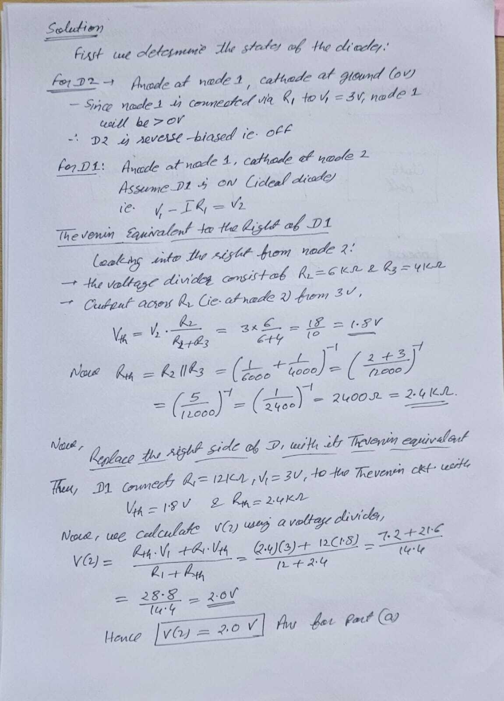
Certainly! Here is the solution rewritten in a more organized manner:
---
## Solution
### First, we determine the states of the diodes:
---
#### For D2:
- **Anode** at node 1, **cathode** at ground (0V)
- Since node 1 is connected via \(R_1\) to \(V_1 = 3V\), node 1 would be \(> 0V\)
- Therefore, D2 is **reverse-biased** (OFF)
---
#### For D1:
- **Anode** at node 1, **cathode** at node 2
- Assume D1 is ON (ideal diode)
- Thus, \( V_1 - I R_1 = V_2 \)
---
### Thevenin Equivalent to the Right of D1
- **Looking into the right from node 2:**
- The voltage divider consists of \( R_2 = 6k\Omega \) and \( R_3 = 4k\Omega \)
- Current across \( R_2 \) (i.e., at node 2) from 3V:
\[
V_{Th} = V_2 = \frac{R_2}{R_2 + R_3} V_{in} = \frac{6}{6+4} \times 3 = \frac{18}{10} = 1.8V
\]
- Now,
\[
R_{Th} = R_2 \parallel R_3 = \left(\frac{1}{6000} + \frac{1}{4000}\right)^{-1} = \left(\frac{2+3}{12000}\right)^{-1} = \left(\frac{5}{12000}\right)^{-1}
\]
\[
= \left(\frac{1}{2400}\right)^{-1} = 2400\Omega = 2.4k\Omega
\]
---
#### Note:
Replace the right side of D1 with its **Thevenin equivalent**.
---
### Then,
D1 connects \( R_1 = 12k\Omega \), \( V_1 = 3V \), to the Thevenin circuit with:
- \( V_{Th} = 1.8V \)
- \( R_{Th} = 2.4k\Omega \)
---
### Now, calculate \( V(2) \) using voltage divider:
\[
V(2) = \frac{R_{Th}V_1 + R_1V_{Th}}{R_1 + R_{Th}}
\]
\[
= \frac{2.4(3) + 12(1.8)}{12 + 2.4} = \frac{7.2 + 21.6}{14.4}
\]
\[
= \frac{28.8}{14.4} = 2.0V
\]
---
**Hence,**
\[
\boxed{V(2) = 2.0V}
\]
(Answer for part (a))
---
VIPSolutions focuses on clear, step‑by‑step explanations so you can learn quickly. Whether you need an AI‑generated walkthrough or a short hint to get unstuck, each solution is organized for fast reading and easy review later.
Search similar questions, compare approaches, and bookmark the best answers for revision. Our goal is simple: quick, reliable study help that feels natural—not noisy.
 VIPSolutions
 ERT es =
Finrt tue Xetesgmen? Le states of Ho olay.
| pa cy 5 Powele af nade 1 7 caltiede at Sound (ov)
— She ede 2 Connect VIR K tov =3v, hades
willl be >oV
Dy og aeverse biased ie OFF
or D1: foarte at nae 1. cathode of nose 2
Assume DL 4% OV Cioleal ia
| tes ¢-F& 2G
| even int tn tell of D1
(eating ike Lor SLE fet node 2:
—+ Hee voltae dives Ssh RE Rs = yen
= Cudbgal aciew A, Cie afnadle VD Laer 3 v,
SS & hts
Ve = FT Se - A
= ~
TE 2 +32
oo ba = Ks = (de) = (5)
5 oT I =1
= = = lao) — 20008 = 2-4.
Nek, . . ~ .
place po HE 5C % 7 \ wit sty Tevonsin pica!
Tow, D1 comes &= 121en Vy = 3, Ho Hue Trevenrn ck wet
Up=18Y & Ry = 2.401
Nope us celenkefe VO way aveltz civics, oe
VG) = Lg Vy Fes Qu) 12018) Le
2+ Ly, AY
SN RET 2060
ry =r
i [FETT] Pr do Pe