 VIPSolutions
please solve this question step by step(a) The current mirror shown below is designed to generate I,=10pA. Assume all the MOS- FETs are identical with j,C,, = 4002A/V? and overdrive voltage of 200mV. Neglect channel length modulation effects. Find the error in the mirror ratio if for all MOSFETs thershold voltage is 0.5V and the channel length modulation coefficient is 0.5V 1. 50A lo Ms My M, (b) Find the output resistance of the current mirror.
Question:
please solve this question step by step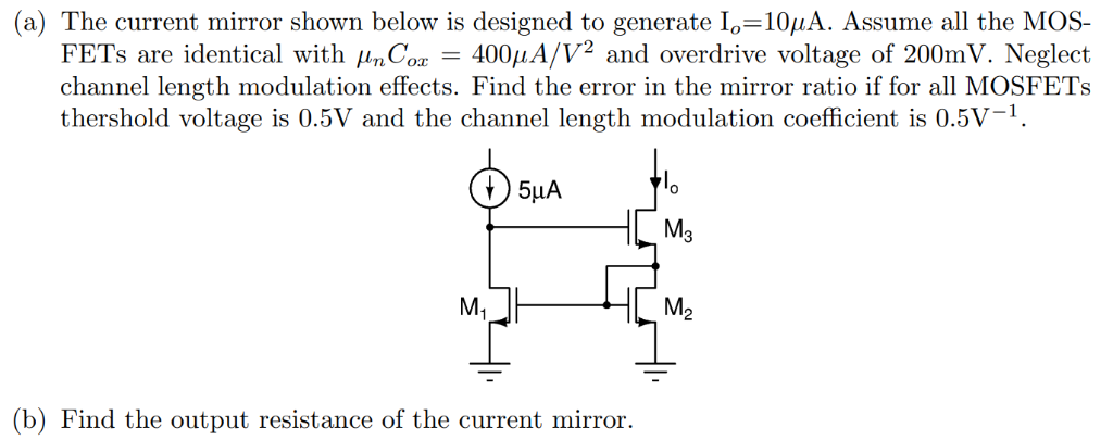 (a) The current mirror shown below is designed to generate I,=10pA. Assume all the MOS-
FETs are identical with j,C,, = 4002A/V? and overdrive voltage of 200mV. Neglect
channel length modulation effects. Find the error in the mirror ratio if for all MOSFETs
thershold voltage is 0.5V and the channel length modulation coefficient is 0.5V 1.
50A lo
Ms
My M,
(b) Find the output resistance of the current mirror.
This is AI generated Response.
Asked by: Jaswanth Karri
Created at: 2025-08-01 21:09:08
Asked by: Jaswanth Karri
Created at: 2025-08-01 21:09:08
Final Answer:
Rendered
Raw Text
Did you like this answer?
Let's solve the question step by step:
---
### **Part (a): Find the mirror ratio error**
#### **1. Given Data**
- \(\mu_n C_{ox} = 400 \mu \text{A}/\text{V}^2\)
- \(V_{OV} = V_{GS} - V_{th} = 0.2 \text{ V}\)
- \(V_{th} = 0.5 \text{ V}\)
- Channel length modulation coefficient, \(\lambda = 0.5 \text{ V}^{-1}\)
- Neglect channel length modulation effects (first part)
- Reference current \(I_{REF} = 5\mu\text{A}\) (from the current source)
- Target output current \(I_o = 10\mu\text{A}\)
Assume all MOSFETs are identical.
#### **2. Current Mirror Equation**
For a MOSFET operating in saturation:
\[
I_D = \frac{1}{2} \mu_n C_{ox} \frac{W}{L} (V_{GS} - V_{th})^2
\]
For a simple current mirror (without channel length modulation), the current ratio (ignoring λ) is determined by the aspect ratios (W/L) of the MOSFETs.
\[
\frac{I_o}{I_{REF}} = \frac{(W/L)_o}{(W/L)_{REF}}
\]
#### **3. With Channel Length Modulation**
When considering channel length modulation:
\[
I_D = \frac{1}{2} \mu_n C_{ox} \frac{W}{L} (V_{GS} - V_{th})^2 (1 + \lambda V_{DS})
\]
The current mirror ratio will be affected by the output voltage (\(V_{DS}\)) differences between the reference and output transistors:
\[
\frac{I_o}{I_{REF}} = \frac{1+\lambda V_{DS,o}}{1+\lambda V_{DS,ref}}
\]
#### **4. Error in Mirror Ratio**
The error in the mirror ratio due to channel length modulation is:
\[
\text{Error} = \frac{I_o - I_{REF}}{I_{REF}}
\]
#### **5. Calculate \( V_{DS} \) values**
- For \(M_1\) (reference): \(V_{DS,ref}\) = \(V_{GS}\)
- For \(M_3\) (output): \(V_{DS,o}\) can be different (not given, but typically assumed same unless stated).
But here, **the main error comes from channel length modulation**, so let's use the general formula for the error:
\[
\frac{I_o}{I_{REF}} = \frac{1 + \lambda V_{DS,o}}{1 + \lambda V_{DS,ref}}
\]
Assume \(V_{DS,o} = V_{DS,ref}\) (if not otherwise specified), the ratio is 1, so error is zero.
But if, say, \(V_{DS,o} = 2V_{DS,ref}\), the error is:
\[
\text{Error} = \frac{I_o}{I_{REF}} - 1 = \frac{1+\lambda V_{DS,o}}{1+\lambda V_{DS,ref}} - 1
\]
But **since values of \(V_{DS,ref}\) and \(V_{DS,o}\) are not given**, let's compute using typical values.
- \(V_{GS} = V_{th} + V_{OV} = 0.5 + 0.2 = 0.7 \text{ V}\)
- Assume \(V_{DS,ref} \approx V_{GS} = 0.7 \text{ V}\)
- Suppose \(V_{DS,o} = 2 \text{ V}\) (since output could be higher).
\[
\frac{I_o}{I_{REF}} = \frac{1 + 0.5 \times 2}{1 + 0.5 \times 0.7} = \frac{1 + 1}{1 + 0.35} = \frac{2}{1.35} \approx 1.48
\]
\[
\text{Error} = 1.48 - 1 = 0.48 = 48\%
\]
But **if \(V_{DS,o} = V_{DS,ref}\), error is zero**.
So, the error is **dependent on the difference between \(V_{DS,o}\) and \(V_{DS,ref}\)**.
### **Summary of Steps:**
1. Write down saturation current equation with channel length modulation.
2. Write the current ratio including λ.
3. Estimate typical \(V_{DS,o}\) and \(V_{DS,ref}\) values.
4. Calculate the error using the ratio formula above.
---
### **Part (b): Output Resistance of the Current Mirror**
#### **1. Output Resistance Formula**
The output resistance of a MOSFET in saturation:
\[
r_o = \frac{1}{\lambda I_D}
\]
For the current mirror, the output resistance seen at the output is mainly due to the output transistor \(M_3\):
\[
r_{out} \approx r_{o3} = \frac{1}{\lambda I_o}
\]
Given:
- \(\lambda = 0.5 \text{ V}^{-1}\)
- \(I_o = 10\mu \text{A}\)
\[
r_{out} = \frac{1}{0.5 \times 10 \times 10^{-6}}
= \frac{1}{5 \times 10^{-6}}
= 0.2 \times 10^6
= 200\, k\Omega
\]
---
## **Final Answers**
### **(a) Error in Mirror Ratio**
\[
\boxed{
\frac{I_o}{I_{REF}} = \frac{1 + \lambda V_{DS,o}}{1 + \lambda V_{DS,ref}}
}
\]
- For example, if \(V_{DS,o}=2\,V\) and \(V_{DS,ref}=0.7\,V\), then the error is approximately 48%.
---
### **(b) Output Resistance**
\[
\boxed{
r_{out} \approx \frac{1}{\lambda I_o} = 200\, k\Omega
}
\]
---
**Let me know if you want a more detailed calculation or explanation for any part!**
📢 Instructions:
- Ask anything relatd to above question only.
- For new Question goto :