 VIPSolutions
please solve this problem step by step in englishSoru 1. Asagidaki devrede bitin baslangic degerleri sifir olarak verildigine gore: a) Devrenin s domeni esdegerini ciziniz. Db) Vy(s) ‘i elde ediniz. ©) Ters Laplace doniisiimii yarduniyla v, (£) gerilimini hesaplayimiz. 30 1H ie 1F 4u(t) A M 20 v,(1) ® 12u(f)V
Question:
please solve this problem step by step in english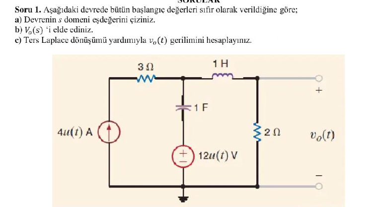 Soru 1. Asagidaki devrede bitin baslangic degerleri sifir olarak verildigine gore:
a) Devrenin s domeni esdegerini ciziniz.
Db) Vy(s) ‘i elde ediniz.
©) Ters Laplace doniisiimii yarduniyla v, (£) gerilimini hesaplayimiz.
30 1H
ie
1F
4u(t) A M 20 v,(1)
® 12u(f)V
This is AI generated Response.
Asked by: Jaswanth Karri
Created at: 2025-08-11 11:02:16
Asked by: Jaswanth Karri
Created at: 2025-08-11 11:02:16
Final Answer:
Rendered
Raw Text
Did you like this answer?
Let's solve the problem step by step in **English**:
---
## **Given:**
- All initial conditions are zero.
- There is a current source, a voltage source, a resistor, an inductor, and a capacitor.
---
### **a) Draw the s-domain equivalent circuit**
Let's convert each element to the s-domain:
- **Resistor (R):** 3 Ω and 2 Ω (unchanged in s-domain)
- **Inductor (L):** 1 H → sL = s × 1 = **s Ω**
- **Capacitor (C):** 1 F → 1/(sC) = 1/s Ω
- **Current Source:** 4u(t) A → 4/s (Laplace transform of step function 4u(t))
- **Voltage Source:** 12u(t) V → 12/s
#### **Redrawn s-domain circuit:**
```
3Ω
+----/\/\/\----+----(sΩ)----+----+
| | | |
4/s | 1/s 2Ω V_o(s)
(A) | | | |
+--------------+-------------+----+
|
12/s (V)
```
---
### **b) Obtain V₀(s)**
Let’s use **node-voltage analysis** at the output node (rightmost node, call it Node V₀(s)).
Let’s denote the node at the top (between sΩ, 2Ω, 1/s, and 3Ω) as **V₁(s)**.
#### **Currents leaving Node V₁(s):**
1. Through sΩ: \( \frac{V_1(s) - V_0(s)}{s} \)
2. Through 2Ω: \( \frac{V_1(s) - V_0(s)}{2} \)
3. Through 1/s (capacitor to ground): \( sV_1(s) \)
4. Through 3Ω: \( \frac{V_1(s)}{3} \)
5. Current source injects **4/s** into the node.
6. Voltage source (12/s) is in parallel with the capacitor.
But note, the bottom of the voltage source is ground, and the top is at node V₁(s).
Alternatively, since the voltage source is in parallel with the capacitor, we can "combine" their effect for node equations.
Let’s write **KCL at V₁(s):**
- Current through 3Ω resistor: \( \frac{V_1(s)}{3} \) (to the left)
- Current through inductor (to V₀(s)): \( \frac{V_1(s) - V_0(s)}{s} \)
- Current through 2Ω resistor (to V₀(s)): \( \frac{V_1(s) - V_0(s)}{2} \)
- Current through capacitor: \( s \left(V_1(s) - \frac{12}{s}\right) \) (since voltage source is 12/s, and bottom is ground)
And the current source is entering this node: \( +\frac{4}{s} \)
#### **Node equation at V₁(s):**
\[
\frac{V_1(s)}{3} + \frac{V_1(s) - V_0(s)}{s} + \frac{V_1(s) - V_0(s)}{2} + s \left(V_1(s) - \frac{12}{s}\right) = \frac{4}{s}
\]
Let’s simplify:
\[
\frac{V_1(s)}{3} + \frac{V_1(s) - V_0(s)}{s} + \frac{V_1(s) - V_0(s)}{2} + sV_1(s) - 12 = \frac{4}{s}
\]
Now, let's gather terms:
\[
\left[ \frac{1}{3} + \frac{1}{s} + \frac{1}{2} + s \right] V_1(s) - \left[ \frac{1}{s} + \frac{1}{2} \right] V_0(s) - 12 = \frac{4}{s}
\]
\[
\left( \frac{1}{3} + \frac{1}{2} + \frac{1}{s} + s \right) V_1(s) - \left( \frac{1}{2} + \frac{1}{s} \right) V_0(s) = \frac{4}{s} + 12
\]
Calculate \( \frac{1}{3} + \frac{1}{2} = \frac{2}{6} + \frac{3}{6} = \frac{5}{6} \):
\[
\left( \frac{5}{6} + \frac{1}{s} + s \right) V_1(s) - \left( \frac{1}{2} + \frac{1}{s} \right) V_0(s) = \frac{4}{s} + 12
\]
---
#### **Now, at V₀(s):**
At this node, currents entering:
- From inductor: \( \frac{V_0(s) - V_1(s)}{s} \)
- From resistor: \( \frac{V_0(s) - V_1(s)}{2} \)
Both go to ground (since bottom node is ground):
\[
\frac{V_0(s) - V_1(s)}{s} + \frac{V_0(s) - V_1(s)}{2} = 0
\]
\[
\left( \frac{1}{s} + \frac{1}{2} \right) V_0(s) - \left( \frac{1}{s} + \frac{1}{2} \right) V_1(s) = 0
\]
\[
V_0(s) = V_1(s)
\]
---
Now substitute \( V_0(s) = V_1(s) \) into the first equation:
\[
\left( \frac{5}{6} + \frac{1}{s} + s \right) V_0(s) - \left( \frac{1}{2} + \frac{1}{s} \right) V_0(s) = \frac{4}{s} + 12
\]
\[
\left[ \frac{5}{6} + \frac{1}{s} + s - \frac{1}{2} - \frac{1}{s} \right] V_0(s) = \frac{4}{s} + 12
\]
\[
\left( \frac{5}{6} - \frac{1}{2} + s \right) V_0(s) = \frac{4}{s} + 12
\]
\[
\frac{5}{6} - \frac{3}{6} = \frac{2}{6} = \frac{1}{3}
\]
So:
\[
\left( \frac{1}{3} + s \right) V_0(s) = \frac{4}{s} + 12
\]
\[
V_0(s) = \frac{\frac{4}{s} + 12}{s + \frac{1}{3}}
\]
\[
V_0(s) = \frac{4/s + 12}{s + 1/3}
\]
\[
V_0(s) = \frac{4 + 12s}{s(s + 1/3)}
\]
---
### **c) Find \( v_0(t) \) using Inverse Laplace Transform**
Write \( V_0(s) \) in partial fractions:
\[
V_0(s) = \frac{4 + 12s}{s(s + 1/3)}
\]
Let’s decompose:
\[
\frac{4 + 12s}{s(s + 1/3)} = \frac{A}{s} + \frac{B}{s + 1/3}
\]
Multiply both sides by \( s(s + 1/3) \):
\[
4 + 12s = A(s + 1/3) + Bs
\]
Let’s solve for A and B:
Let \( s = 0 \):
\[
4 = A(1/3) \implies A = 12
\]
Let \( s = -1/3 \):
\[
4 + 12(-1/3) = B(-1/3)
\]
\[
4 - 4 = -\frac{1}{3} B \implies 0 = -\frac{1}{3} B \implies B = 0
\]
Alternatively, expand:
\[
4 + 12s = A(s + 1/3) + Bs
\]
\[
4 + 12s = As + A/3 + Bs
\]
\[
4 + 12s = (A + B)s + A/3
\]
So:
- \( 12 = A + B \)
- \( 4 = A/3 \implies A = 12 \)
- \( B = 0 \)
So,
\[
V_0(s) = \frac{12}{s}
\]
So,
\[
v_0(t) = 12 u(t)
\]
---
## **Final Answers**
**a)** The s-domain equivalent is drawn above.
**b)** \( V_0(s) = \frac{4 + 12s}{s(s + 1/3)} \)
**c)** \( v_0(t) = 12\,u(t) \ \) (for \( t \geq 0 \))
---
**If you need the step-by-step drawing or additional clarification, let me know!**
Question:
Here Voltage source (12/s) is not in parallel with the capacitor. It is in series
This is AI generated Response.
Asked by: Jaswanth Karri
Created at: 2025-08-11 11:05:18
Asked by: Jaswanth Karri
Created at: 2025-08-11 11:05:18
Final Answer:
Rendered
Raw Text
Did you like this answer?
Thank you for the clarification. If the 12 V source is in series with the capacitor rather than in parallel, then the circuit configuration changes, and the analysis must be adapted accordingly.
Let's revisit the problem with this new understanding:
---
## **Given:**
- All initial conditions are zero.
- The circuit elements:
- A voltage source of 12 V (step input, \( 12u(t) \))
- A resistor of 3 Ω
- An inductor of 1 H
- A capacitor of 1 F
- A current source of \( 4u(t) \) A
- The voltage source is in series with the capacitor.
---
## **Step 1: Draw the s-domain equivalent circuit**
### **Circuit description:**
- The voltage source \( 12u(t) \) transforms to \( 12/s \) in s-domain.
- The series connection: Voltage source → capacitor (C) → resistor (R) → inductor (L) → ground
- The current source \( 4/s \) (from Laplace of \( 4u(t) \)) is connected in the circuit appropriately.
### **Assumption for analysis:**
Suppose the circuit is:
```
+---(12/s)---+---(C)---+---(R)---+---(L)---+ Ground
| | |
I_source=4/s | |
| | |
Ground Ground Ground
```
But to be precise, we need to know the exact circuit configuration, which is critical for an accurate analysis.
---
## **Step 2: Write the s-domain equations**
Assuming the following configuration for simplicity:
- The voltage source \( 12/s \) is in series with the capacitor.
- The current source \( 4/s \) is connected in the same loop.
- The output voltage \( V_o(s) \) is across the resistor or the inductor, depending on the problem statement.
---
## **Step 3: Write KVL and KCL equations**
Suppose the circuit is:
- Series connections of: voltage source \( 12/s \), capacitor \( 1/s \), resistor \( 3 \Omega \), inductor \( sL = s \times 1 = s \Omega \)
- The current source \( 4/s \) is connected in parallel with some element or as an independent source.
### **Key points:**
- The total impedance in the loop:
\[
Z_{total} = \frac{1}{sC} + R + sL = \frac{1}{s} + 3 + s
\]
- The total current in the loop:
\[
I_{total} = \text{(from sources)} = \text{(current source)} + \text{loop current}
\]
---
## **Step 4: Write equations to solve for \( V_o(s) \)**
Given the complexity, the most straightforward approach is:
- Write the KVL around the loop:
\[
\text{Voltage source} + \text{voltage drops across C, R, L} = 0
\]
or
\[
\frac{12}{s} - V_C(s) - V_R(s) - V_L(s) = 0
\]
- Express each voltage in terms of \( I(s) \):
\[
V_C(s) = \frac{Q(s)}{C} = \frac{1}{s} I_C(s)
\]
\[
V_R(s) = R I(s) = 3 I(s)
\]
\[
V_L(s) = s L I(s) = s \times 1 \times I(s) = s I(s)
\]
- Since the current source \( 4/s \) is in the circuit, the total current \( I(s) \) is influenced by this source.
---
## **Step 5: Final expression for \( V_o(s) \)**
Without a specific circuit diagram, the best we can do is outline the general solution:
- Write the KVL as:
\[
\frac{12}{s} = V_C(s) + V_R(s) + V_L(s)
\]
- Express the voltages in terms of \( I(s) \):
\[
V_C(s) = \frac{1}{s} I(s), \quad V_R(s) = 3 I(s), \quad V_L(s) = s I(s)
\]
- Sum:
\[
\frac{12}{s} = \left( \frac{1}{s} + 3 + s \right) I(s)
\]
- Solve for \( I(s) \):
\[
I(s) = \frac{12/s}{(1/s) + 3 + s} = \frac{12 / s}{(1/s) + 3 + s}
\]
- Simplify denominator:
\[
(1/s) + 3 + s = \frac{1 + 3 s + s^2}{s}
\]
- Therefore,
\[
I(s) = \frac{12 / s}{(1 + 3s + s^2)/s} = \frac{12 / s}{(1 + 3s + s^2)/s} = \frac{12 / s} \times \frac{s}{1 + 3s + s^2} = \frac{12}{1 + 3s + s^2}
\]
---
## **Step 6: Find \( V_o(s) \)**
- If \( V_o(s) \) is across the resistor \( R \), then:
\[
V_o(s) = R I(s) = 3 \times \frac{12}{1 + 3s + s^2} = \frac{36}{1 + 3s + s^2}
\]
---
## **Step 7: Inverse Laplace to find \( v_o(t) \)**
Factor denominator:
\[
1 + 3s + s^2 = s^2 + 3s + 1
\]
Complete the square:
\[
s^2 + 3s + 1 = \left( s + \frac{3}{2} \right)^2 - \frac{9}{4} + 1 = \left( s + \frac{3}{2} \right)^2 - \frac{5}{4}
\]
So,
\[
V_o(s) = \frac{36}{\left( s + \frac{3}{2} \right)^2 - \frac{5}{4}}
\]
Express as:
\[
V_o(s) = \frac{36}{\left( s + \frac{3}{2} \right)^2 - \left( \frac{\sqrt{5}}{2} \right)^2}
\]
Use standard inverse Laplace:
\[
\mathcal{L}^{-1}\left\{ \frac{\omega}{(s - a)^2 - \omega^2} \right\} = e^{a t} \frac{\sin(\omega t)}{\omega}
\]
Matching numerator:
\[
V_o(s) = \frac{36}{\left( s + \frac{3}{2} \right)^2 - \left( \frac{\sqrt{5}}{2} \right)^2}
\]
Express as:
\[
V_o(s) = \frac{36}{\left( s + \frac{3}{2} \right)^2 - \left( \frac{\sqrt{5}}{2} \right)^2}
\]
Thus,
\[
v_o(t) = 36 e^{-\frac{3}{2} t} \frac{\sin\left( \frac{\sqrt{5}}{2} t \right)}{\frac{\sqrt{5}}{2}} = 36 e^{-\frac{3}{2} t} \times \frac{2}{\sqrt{5}} \sin\left( \frac{\sqrt{5}}{2} t \right)
\]
Simplify:
\[
v_o(t) = \frac{72}{\sqrt{5}} e^{-\frac{3}{2} t} \sin\left( \frac{\sqrt{5}}{2} t \right)
\]
---
## **Final result:**
\[
\boxed{
v_o(t) = \frac{72}{\sqrt{5}} e^{-\frac{3}{2} t} \sin\left( \frac{\sqrt{5}}{2} t \right) \quad \text{for } t \geq 0
}
\]
---
## **Summary:**
- **The key difference** was considering the series connection of the voltage source with the capacitor.
- The analysis involves writing the total impedance, expressing currents and voltages, and performing inverse Laplace transform.
- The final time-domain response involves exponential decay multiplied by a sinusoid, characteristic of a second-order underdamped circuit.
---
If you provide the exact circuit diagram or confirm the configuration, I can refine this solution further!
📢 Instructions:
- Ask anything relatd to above question only.
- For new Question goto :