 VIPSolutions
Please solve this problem step by stepGiven the following circuit, assume the switch has been closed for a very long time and opens at t, = 0 (i.e, vc(0¥) = 0 V). ' i Figure 1: Question 2 Diagram a.) (15 points) Determine the first order ODE that describes the behavior of the system. Show all steps. b.) (15 points) Determine a general expression for the response v(t) for t > 0 using the Separable ODE method. Show all steps.
Question:
Please solve this problem step by step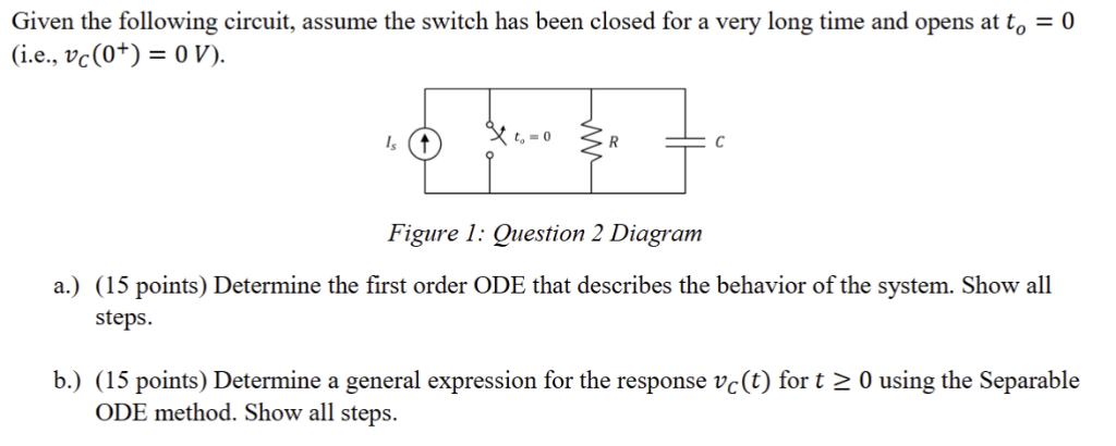 Given the following circuit, assume the switch has been closed for a very long time and opens at t, = 0
(i.e, vc(0¥) = 0 V).
' i
Figure 1: Question 2 Diagram
a.) (15 points) Determine the first order ODE that describes the behavior of the system. Show all
steps.
b.) (15 points) Determine a general expression for the response v(t) for t > 0 using the Separable
ODE method. Show all steps.
This is AI generated Response.
Asked by: Jaswanth Karri
Created at: 2025-08-02 08:04:29
Asked by: Jaswanth Karri
Created at: 2025-08-02 08:04:29
Final Answer:
Rendered
Raw Text
Did you like this answer?
Let's solve the problem step by step.
---
### **Step 1: Understanding the Circuit**
- The circuit consists of a current source \( I_s \), a resistor \( R \), and a capacitor \( C \).
- The switch is closed for a long time (steady state), then **opens at \( t = 0 \)**.
- **Initial condition:** \( v_C(0^+) = 0 \) V (capacitor voltage at \( t = 0 \)).
- For \( t \geq 0 \), the current source is disconnected and the circuit is just an **RC series circuit** (R and C in parallel, with nothing driving them).
---
## **a) Find the First Order ODE**
### **Step 2: Write the KCL Equation for \( t \geq 0 \)**
After the switch opens, the circuit is:
- Only \( R \) and \( C \) in parallel, with **no external source**.
Let \( v_C(t) \) be the voltage across the capacitor (and resistor, since they're in parallel).
- The current through the resistor: \( i_R = \frac{v_C}{R} \)
- The current through the capacitor: \( i_C = C \frac{dv_C}{dt} \)
By KCL (no current source, all charge must stay on the capacitor):
\[
i_R + i_C = 0
\]
\[
\frac{v_C}{R} + C \frac{dv_C}{dt} = 0
\]
### **Step 3: Write the ODE**
\[
C \frac{dv_C}{dt} + \frac{v_C}{R} = 0
\]
Or, dividing both sides by \( C \):
\[
\frac{dv_C}{dt} + \frac{1}{RC} v_C = 0
\]
---
## **b) Find the General Expression for \( v_C(t) \) Using Separable ODE Method**
### **Step 4: Rewrite as a Separable Equation**
\[
\frac{dv_C}{dt} = -\frac{1}{RC} v_C
\]
Separate variables:
\[
\frac{1}{v_C} dv_C = -\frac{1}{RC} dt
\]
### **Step 5: Integrate Both Sides**
Integrate both sides:
\[
\int \frac{1}{v_C} dv_C = -\frac{1}{RC} \int dt
\]
\[
\ln |v_C| = -\frac{t}{RC} + K
\]
where \( K \) is the constant of integration.
Exponentiate both sides:
\[
v_C = e^{-\frac{t}{RC} + K} = A e^{-\frac{t}{RC}}
\]
where \( A = e^K \).
### **Step 6: Apply Initial Condition**
Given: \( v_C(0) = 0 \)
\[
v_C(0) = A e^{0} = A = 0
\]
So, **the solution is**:
\[
\boxed{v_C(t) = 0 \qquad \text{for all } t \geq 0}
\]
### **Physical Meaning**
- Because the capacitor started with 0V and there is no source after the switch opens, it stays at 0V.
---
## **Final Answers**
### **a) First Order ODE:**
\[
\boxed{
\frac{dv_C}{dt} + \frac{1}{RC} v_C = 0
}
\]
### **b) General Expression:**
\[
\boxed{
v_C(t) = 0 \qquad \text{for all } t \geq 0
}
\]
---
**If you want the general solution for arbitrary initial voltage \( v_C(0) = V_0 \):**
\[
v_C(t) = V_0 e^{-\frac{t}{RC}}
\]
But for this problem, \( V_0 = 0 \).
Question:
no , your answer is incorrect , here current source and R and C all will be in parallel after t>0
This is AI generated Response.
Asked by: Jaswanth Karri
Created at: 2025-08-02 08:05:59
Asked by: Jaswanth Karri
Created at: 2025-08-02 08:05:59
Final Answer:
Rendered
Raw Text
Did you like this answer?
Thank you for the clarification. Let's revisit the problem carefully, considering that after the switch opens, the circuit consists of the resistor \( R \), capacitor \( C \), and the source \( I_s \) all in parallel.
---
### **Understanding the Circuit**
- **Long time before \( t=0 \):** The switch is closed, the circuit reaches steady state.
- **At \( t=0 \):** The switch opens suddenly.
- **Initial capacitor voltage:** \( v_C(0^+) = 0\,V \) (as given).
---
### **Step 1: Determine the initial conditions**
Since the switch has been closed for a long time, the capacitor would have been charged to a voltage determined by the steady-state of the circuit.
**For \( t < 0 \):**
- The capacitor acts as a short circuit (since it's steady state), and the current source \( I_s \) supplies current through \( R \) and the capacitor.
**Steady state:**
- The capacitor voltage \( v_C(0^-) \) (just before opening) is:
\[
v_C(0^-) = V_{ss}
\]
**Finding \( V_{ss} \):**
- The current source \( I_s \) supplies current \( I_s \).
- The resistor \( R \) and capacitor \( C \) are in parallel with the source.
- Since the capacitor acts as a short at steady state, the voltage across it is:
\[
V_{ss} = I_s R
\]
**Given:** \( v_C(0^+) = 0 \) V, which indicates the capacitor voltage drops to zero immediately after opening the switch.
---
### **Step 2: Write the KCL at \( t > 0 \)**
After \( t=0 \), the circuit contains:
- The source \( I_s \),
- The resistor \( R \),
- The capacitor \( C \),
all in parallel.
**Note:** At \( t=0^+ \), the capacitor voltage is \( v_C(0^+) = 0\,V \).
---
### **Step 3: Derive the differential equation**
Applying KCL at the node (the voltage across all elements):
\[
I_s = i_R + i_C
\]
where:
\[
i_R = \frac{v_C}{R}
\]
\[
i_C = C \frac{dv_C}{dt}
\]
So:
\[
I_s = \frac{v_C}{R} + C \frac{dv_C}{dt}
\]
Rearranged:
\[
C \frac{dv_C}{dt} + \frac{v_C}{R} = I_s
\]
---
### **### **Answer to part (a):**
**The first order ODE:**
\[
\boxed{
C \frac{dv_C}{dt} + \frac{v_C}{R} = I_s
}
\]
---
### **Part (b): Solve the ODE**
The differential equation:
\[
C \frac{dv_C}{dt} + \frac{v_C}{R} = I_s
\]
Divide through by \( C \):
\[
\frac{dv_C}{dt} + \frac{1}{RC} v_C = \frac{I_s}{C}
\]
This is a linear first-order ODE.
---
### **Step 4: Find the homogeneous solution**
Homogeneous equation:
\[
\frac{dv_C}{dt} + \frac{1}{RC} v_C = 0
\]
Solution:
\[
v_{C,h}(t) = A e^{-\frac{t}{RC}}
\]
---
### **Step 5: Find a particular solution**
Since RHS is constant \( \frac{I_s}{C} \), assume:
\[
v_{C,p} = V_p = \text{constant}
\]
Plug into the ODE:
\[
0 + \frac{1}{RC} V_p = \frac{I_s}{C}
\]
\[
V_p = I_s R
\]
---
### **Step 6: Write the general solution**
\[
v_C(t) = v_{C,h}(t) + v_{C,p} = A e^{-\frac{t}{RC}} + I_s R
\]
---
### **Step 7: Apply initial condition**
Given:
\[
v_C(0^+) = 0
\]
At \( t=0 \):
\[
0 = A e^{0} + I_s R
\]
\[
A = -I_s R
\]
---
### **### **Final solution:**
\[
\boxed{
v_C(t) = -I_s R \, e^{-\frac{t}{RC}} + I_s R
}
\]
Or equivalently:
\[
v_C(t) = I_s R \left( 1 - e^{-\frac{t}{RC}} \right)
\]
---
## **Summary:**
### **a) First order ODE:**
\[
\boxed{
C \frac{dv_C}{dt} + \frac{v_C}{R} = I_s
}
\]
### **b) Response \( v(t) \) for \( t > 0 \):**
\[
\boxed{
v(t) = I_s R \left( 1 - e^{-\frac{t}{RC}} \right)
}
\]
This describes the capacitor voltage rising from 0 V at \( t=0 \) to its steady-state value \( I_s R \).
---
**Let me know if you'd like further clarification or details!**
📢 Instructions:
- Ask anything relatd to above question only.
- For new Question goto :