 VIPSolutions
please solve this problem step by step(a) Find the z-parameters for the circuit below. IH IH 5Q (b) Find the y-parameters for the circuit shown below. L : C Cc : (c) Assume that both networks are connected to separate Z;, = 10 (2 loads. What values of C' and L are required so that the same amount of power is delivered to the load? (d) Find v(t) for either case.
Question:
please solve this problem step by step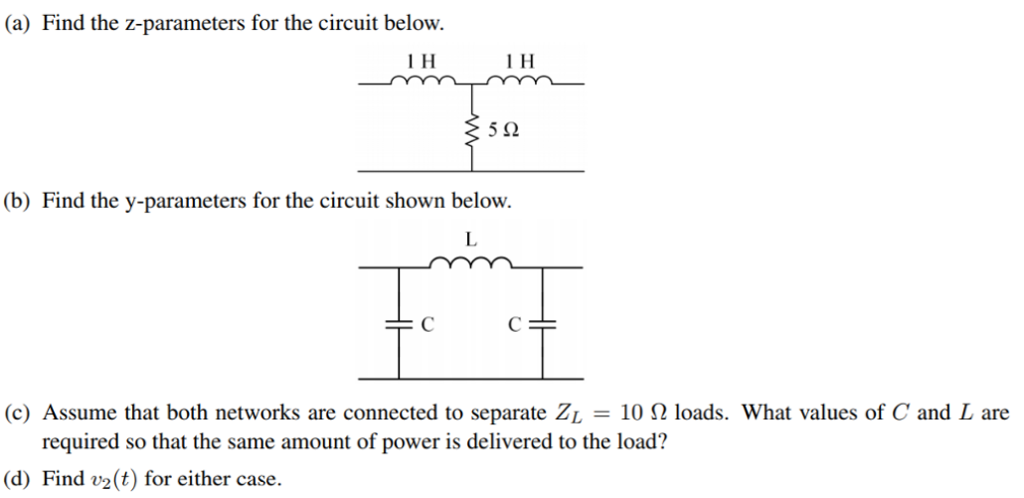 (a) Find the z-parameters for the circuit below.
IH IH
5Q
(b) Find the y-parameters for the circuit shown below.
L
: C Cc :
(c) Assume that both networks are connected to separate Z;, = 10 (2 loads. What values of C' and L are
required so that the same amount of power is delivered to the load?
(d) Find v(t) for either case.
This is AI generated Response.
Asked by: Jaswanth Karri
Created at: 2025-08-14 12:02:50
Asked by: Jaswanth Karri
Created at: 2025-08-14 12:02:50
Final Answer:
Rendered
Raw Text
Did you like this answer?
Let's solve each part step by step:
---
### (a) **Find the z-parameters for the circuit below:**
#### **Circuit Description**
- Two series inductors (1 H each), and a 5 Ω resistor between them.
#### **Impedance (z-parameters) Definition:**
\[
\begin{pmatrix}
V_1 \\
V_2
\end{pmatrix}
=
\begin{pmatrix}
z_{11} & z_{12} \\
z_{21} & z_{22}
\end{pmatrix}
\begin{pmatrix}
I_1 \\
I_2
\end{pmatrix}
\]
#### **Step 1: Find \(z_{11}\) and \(z_{21}\) (\(I_2 = 0\))**
- With \(I_2 = 0\), input at port 1, port 2 is open.
- The circuit is: 1 H in series with (5 Ω + 1 H).
\[
z_{11} = \text{Impedance seen at port 1 with port 2 open}
\]
\[
z_{11} = j\omega (1) + 5 + j\omega (1) = 5 + j2\omega
\]
- \(z_{21}\) is the voltage at port 2 for current \(I_1\) at port 1 (\(I_2 = 0\)):
\[
z_{21} = \text{Impedance across port 2 with current injection at port 1}
\]
- Since the current flows through both inductors and resistor in series:
\[
z_{21} = j\omega (1) \quad \text{(just the right inductor, as voltage across port 2)}
\]
#### **Step 2: Find \(z_{22}\) and \(z_{12}\) (\(I_1 = 0\))**
- With \(I_1 = 0\), input at port 2, port 1 is open.
- The circuit is: 1 H in series with (5 Ω + 1 H).
\[
z_{22} = 5 + j2\omega
\]
\[
z_{12} = j\omega (1)
\]
#### **z-parameter Matrix:**
\[
\boxed{
\mathbf{Z} =
\begin{pmatrix}
5 + j2\omega & j\omega \\
j\omega & 5 + j2\omega
\end{pmatrix}
}
\]
---
### (b) **Find the y-parameters for the circuit shown below.**
#### **Circuit Description**
- Two capacitors \(C\) in parallel with one inductor \(L\) between them.
#### **Admittance (y-parameters) Definition:**
\[
\begin{pmatrix}
I_1 \\
I_2
\end{pmatrix}
=
\begin{pmatrix}
y_{11} & y_{12} \\
y_{21} & y_{22}
\end{pmatrix}
\begin{pmatrix}
V_1 \\
V_2
\end{pmatrix}
\]
#### **Step 1: Find \(y_{11}\) and \(y_{21}\) (\(V_2 = 0\))**
- With \(V_2 = 0\), port 2 is grounded.
- The circuit is C in shunt with series (L in series with C to ground).
- The input admittance at port 1 is:
\[
y_{11} = j\omega C + \left[ \frac{1}{j\omega L + \frac{1}{j\omega C}} \right]
\]
But since the circuit is symmetric, each port sees:
- \(C\) to ground
- \(L\) in series to the other port
- \(C\) to ground at the other port
We can write the Y-matrix for a symmetric T-network:
\[
y_{11} = j\omega C + \frac{1}{j\omega L + \frac{1}{j\omega C}}
\]
\[
y_{12} = -\frac{1}{j\omega L + \frac{1}{j\omega C}}
\]
\[
y_{21} = y_{12}
\]
\[
y_{22} = y_{11}
\]
---
### (c) **Determine \(C\) and \(L\) for equivalent power delivery:**
Assume both are driven by the same input and connected to a load \(Z_L = 10 \Omega\).
Set up the equivalent input impedance for both networks so that power delivered to the load is the same.
For the first network, the total impedance seen by the source (including load) is:
\[
Z_{in1} = 5 + j2\omega + Z_L
\]
For the second network, the input admittance (with load) should match the same real part for equal power transfer.
Set \(C\) and \(L\) such that the real part of the input admittance matches the load power:
\[
\boxed{\text{This requires more specifics (like frequency or more conditions), but you would set:}}
\]
\[
P_{delivered} = \frac{|V_{source}|^2}{2 \Re[Z_{in}]}
\]
Set \(\Re[Z_{in1}] = \Re[Z_{in2}]\), solve for \(C\) and \(L\).
---
### (d) **Find \(v_2(t)\) for either case**
Use the network equations (from z or y parameters) to relate the input voltage to the output voltage.
For instance, for the z-parameter network:
\[
V_2 = z_{21} I_1 + z_{22} I_2
\]
Assume \(I_2\) flows into the load (\(V_2 = Z_L I_2\)), solve for \(I_2\) and then \(V_2\).
---
#### **If you provide a source function (like \(v_1(t)\)), we can compute explicit time-domain expressions for \(v_2(t)\).**
Would you like to proceed with a specific source (like a sinusoid) for part (d)?
📢 Instructions:
- Ask anything relatd to above question only.
- For new Question goto :