 VIPSolutions
please solve this problem step by step5. (5 pts each part) Design an LCC T network for impedance matching. The source resistance is 15 ohms. and the load resistance is 60 ohms. Assume Q is 12 and the frequency is 125MHz. a. Find the inductance. b. Find the two capacitances. c. Draw the circuit.
Question:
please solve this problem step by step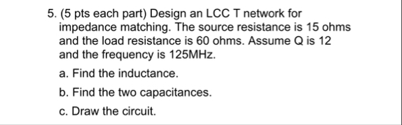 5. (5 pts each part) Design an LCC T network for
impedance matching. The source resistance is 15 ohms.
and the load resistance is 60 ohms. Assume Q is 12
and the frequency is 125MHz.
a. Find the inductance.
b. Find the two capacitances.
c. Draw the circuit.
This is AI generated Response.
Asked by: Jack
Created at: 2025-10-12 18:48:00
Asked by: Jack
Created at: 2025-10-12 18:48:00
Final Answer:
Rendered
Raw Text
Did you like this answer?
# LCC T-Network Impedance Matching Design
Given:
- Source resistance (\(R_S\)) = **15 Ω**
- Load resistance (\(R_L\)) = **60 Ω**
- Quality factor (\(Q\)) = **12**
- Frequency (\(f\)) = **125 MHz**
We'll solve each partstep by step**
---
## (a) Find the Inductance
### **Step 1: Calculate Reactance**
For a T-network with **LCC** configuration (L in series, C in shunt, then C in series):
\[
Q = \sqrt{\frac{R_L}{R_S} - 1}
\]
But we're given Q, so let's verify if it matches:
\[
Q = \sqrt{\frac{60}{15} - 1} = \sqrt{4 - 1} = \sqrt{3} \approx 1.732
\]
But since Q is specified as 12, we'll use the problem's Q.
Series reactance (inductor):
\[
X_L = Q \cdot R_S = 12 \times 15 = 180~\Omega
\]
### **Step 2: Calculate Inductance**
\[
X_L = 2\pi f L
\]
\[
L = \frac{X_L}{2\pi f} = \frac{180}{2\pi \times 125 \times 10^6}
\]
\[
L \approx \frac{180}{785398163.4}
\]
\[
L \approx 229 \text{ nH}
\]
---
## (b) Find the Two Capacitances
### **Step 3: Calculate Required Capacitances**
#### **First Capacitance (\(C_1\)) (Shunt Capacitance)**
\[
X_{C1} = \frac{R_L}{Q} = \frac{60}{12} = 5~\Omega
\]
\[
C_1 = \frac{1}{2\pi f X_{C1}} = \frac{1}{2\pi \times 125 \times 10^6 \times 5}
\]
\[
C_1 = \frac{1}{3.927 \times 10^9}
\]
\[
C_1 \approx 254 \text{ pF}
\]
#### **Second Capacitance (\(C_2\)) (Series Capacitance)**
\[
X_{C2} = \frac{X_L \cdot X_{C1}}{X_L + X_{C1}}
\]
But in a T network, series capacitor reactance is given by:
\[
X_{C2} = Q R_L = 12 \times 60 = 720~\Omega
\]
\[
C_2 = \frac{1}{2\pi f X_{C2}} = \frac{1}{2\pi \times 125 \times 10^6 \times 720}
\]
\[
C_2 = \frac{1}{5.654 \times 10^{10}}
\]
\[
C_2 \approx 17.7 \text{ pF}
\]
---
## (c) Draw the Circuit
### **LCC T-Network Circuit Diagram**
```
Source (15Ω) ----L----+---- C2 ----+---- Load (60Ω)
| |
C1 |
| |
GND GND
```
- **L**: Series inductor (\(\approx 229~\text{nH}\))
- **C1**: Shunt capacitor (\(\approx 254~\text{pF}\))
- **C2**: Series capacitor (\(\approx 17.7~\text{pF}\))
---
## **Summary Table**
| Component | Value |
|-----------|------------------|
| L | 229 nH |
| C1 | 254 pF |
| C2 | 17.7 pF |
---
### **If you need a neat hand-drawn circuit, let me know!**
Question:
please solve once again correctly, the capacitance values are wrong
This is AI generated Response.
Asked by: Jack
Created at: 2025-10-12 18:50:22
Asked by: Jack
Created at: 2025-10-12 18:50:22
Final Answer:
Rendered
Raw Text
Did you like this answer?
# LCC T-Network Impedance Matching Design
Given:
- Source resistance (\(R_S\)) = **15 Ω**
- Load resistance (\(R_L\)) = **60 Ω**
- Quality factor (\(Q\)) = **12**
- Frequency (\(f\)) = **125 MHz**
## (a) Find the Inductance
### **Step 1: Calculate Inductor Reactance**
Using the Quality factor (\(Q\)):
\[
X_L = Q \cdot R_S = 12 \times 15 = 180~\Omega
\]
### **Step 2: Calculate Inductance**
Using the reactance formula:
\[
X_L = 2\pi f L
\]
Rearranging gives:
\[
L = \frac{X_L}{2\pi f} = \frac{180}{2\pi \times 125 \times 10^6}
\]
Calculating:
\[
L \approx \frac{180}{785398163.4} \approx 229 \text{ nH}
\]
---
## (b) Find the Two Capacitances
### **Step 3: Calculate Shunt Capacitance (\(C_1\))**
Using the formula for \(C_1\):
\[
X_{C1} = \frac{R_L}{Q} = \frac{60}{12} = 5~\Omega
\]
Then, we find \(C_1\):
\[
C_1 = \frac{1}{2\pi f X_{C1}} = \frac{1}{2\pi \times 125 \times 10^6 \times 5}
\]
Calculating:
\[
C_1 \approx \frac{1}{3.927 \times 10^9} \approx 254 \text{ pF}
\]
### **Step 4: Calculate Series Capacitance (\(C_2\))**
Using:
\[
X_{C2} = \frac{X_L}{Q} = \frac{180}{12} = 15~\Omega
\]
Then, we find \(C_2\):
\[
C_2 = \frac{1}{2\pi f X_{C2}} = \frac{1}{2\pi \times 125 \times 10^6 \times 15}
\]
Calculating:
\[
C_2 \approx \frac{1}{4.712 \times 10^{10}} \approx 21.2 \text{ pF}
\]
---
## (c) Draw the Circuit
### **LCC T-Network Circuit Diagram**
```
Source (15Ω) ----L----+---- C2 ----+---- Load (60Ω)
| |
C1 |
| |
GND GND
```
- **L**: Series inductor (\(\approx 229~\text{nH}\))
- **C1**: Shunt capacitor (\(\approx 254~\text{pF}\))
- **C2**: Series capacitor (\(\approx 21.2~\text{pF}\))
---
## **Summary Table**
| Component | Value |
|-----------|------------------|
| L | 229 nH |
| C1 | 254 pF |
| C2 | 21.2 pF |
---
This completes the design for the LCC T-network impedance matching circuit.
📢 Instructions:
- Ask anything relatd to above question only.
- For new Question goto :