 VIPSolutions
please solve this problem step by step1. Obtain the state model for a system represented by an electrical network shown in the figure below. Choose Voltages across the capacitors as State Variables. ----[3] R R BRE ip |
Question:
please solve this problem step by step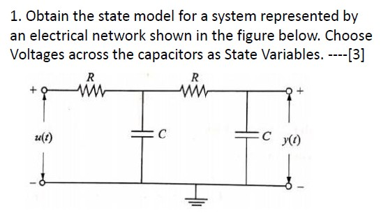 1. Obtain the state model for a system represented by
an electrical network shown in the figure below. Choose
Voltages across the capacitors as State Variables. ----[3]
R R
BRE ip
|
This is AI generated Response.
Asked by: Mohin
Created at: 2025-10-19 07:46:38
Asked by: Mohin
Created at: 2025-10-19 07:46:38
Final Answer:
Rendered
Raw Text
Did you like this answer?
Let's carefully analyze given circuit and the state model by step.
# Circuit Description- The circuit:
- resistors \( R) in series - Twoitors \( C) connected in parallel with the resistors.
- Input voltage \( u(t) \) applied at the left.
- Output voltage \( y(t) \) at the right.
- Grounded at the bottom.
---
# Step 1: Define State Variables
The capacitors store energy, so the voltages across the capacitors are natural choices for state variables:
\[
x_1(t) = v_{C_1}(t), \quad x_2(t) = v_{C_2}(t)
\]
---
# Step 2: Write KCL at each node
### Node at the left of \( C \):
- The current through \( R \) from input to node: \( \frac{u(t) - v_{C_1}(t)}{R} \)
- The current through \( C_1 \): \( C \frac{dv_{C_1}}{dt} \)
Applying KCL:
\[
\frac{u(t) - v_{C_1}}{R} = C \frac{dv_{C_1}}{dt}
\]
Rearranged:
\[
C \frac{dv_{C_1}}{dt} = \frac{u(t) - v_{C_1}}{R}
\]
Similarly, for the node between \( C_1 \) and \( C_2 \):
- The current through \( R \) from \( v_{C_1} \) to \( v_{C_2} \): \( \frac{v_{C_1} - v_{C_2}}{R} \)
- The current through \( C_2 \): \( C \frac{dv_{C_2}}{dt} \)
Applying KCL:
\[
\frac{v_{C_1} - v_{C_2}}{R} = C \frac{dv_{C_2}}{dt}
\]
---
# Step 3: Write the state equations
Expressed as differential equations:
\[
\boxed{
\begin{aligned}
C \frac{dx_1}{dt} &= \frac{u(t) - x_1}{R} \\
C \frac{dx_2}{dt} &= \frac{x_1 - x_2}{R}
\end{aligned}
}
\]
which simplifies to:
\[
\boxed{
\begin{aligned}
\frac{dx_1}{dt} &= - \frac{1}{RC} x_1 + \frac{1}{RC} u(t) \\
\frac{dx_2}{dt} &= \frac{1}{RC} x_1 - \frac{1}{RC} x_2
\end{aligned}
}
\]
---
# Step 4: Output Equation
The output voltage \( y(t) \) is the voltage across the second capacitor:
\[
y(t) = v_{C_2} = x_2(t)
\]
---
# **Final State-Space Model**
\[
\boxed{
\begin{aligned}
\dot{\mathbf{x}}(t) &= A \mathbf{x}(t) + B u(t) \\
y(t) &= C \mathbf{x}(t)
\end{aligned}
}
\]
where
\[
A = \begin{bmatrix}
-\frac{1}{RC} & \\
\frac{1}{RC} & -\frac{1}{RC}
\end{bmatrix},
\quad
B = \begin{bmatrix}
\frac{1}{RC} \\
\end{bmatrix},
\quad
C = \begin{bmatrix}
& 1
\end{bmatrix}
\]
---
Let me know if you'd like me to clarify any step or proceed further!
📢 Instructions:
- Ask anything relatd to above question only.
- For new Question goto :