 VIPSolutions
please solve this problem step by step3. Fig. 3 shows the basic difference amplifier. Assume that all the OP-AMPs used in the following questions are ideal, please answer the following questions. (¢) For Fig. 3, by connecting vi and vp to a common-mode signal Vic, the common- mode gain (Ac) which is defined as vo/vicw can be obtained. Please express iz, v- (non-inverting node of the OP-AMP) and Vo in terms of Vim and resistors. (3 points for iz, 3 points for V+ and 5 points for vo) i | R, 2 2 3 R, Un Ry LL] : Yo Ry
Question:
please solve this problem step by step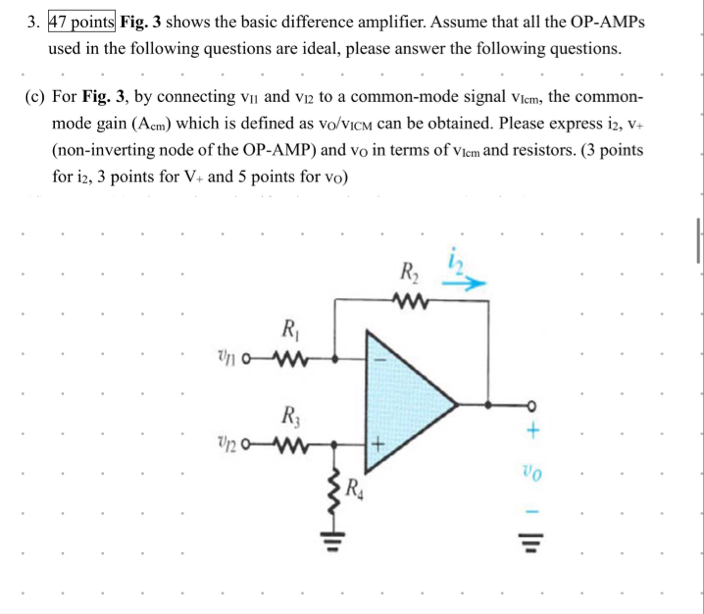 3. Fig. 3 shows the basic difference amplifier. Assume that all the OP-AMPs
used in the following questions are ideal, please answer the following questions.
(¢) For Fig. 3, by connecting vi and vp to a common-mode signal Vic, the common-
mode gain (Ac) which is defined as vo/vicw can be obtained. Please express iz, v-
(non-inverting node of the OP-AMP) and Vo in terms of Vim and resistors. (3 points
for iz, 3 points for V+ and 5 points for vo)
i |
R, 2
2 3
R,
Un
Ry
LL] :
Yo
Ry
This is AI generated Response.
Asked by: Mohin
Created at: 2025-10-20 08:23:43
Asked by: Mohin
Created at: 2025-10-20 08:23:43
Final Answer:
Rendered
Raw Text
Did you like this answer?
Let's solve the problem step-by-step.
---
## **Given Data and Assumptions**
- The is a basic difference amplifier.
- OP-AMPs are ideal.
The question involves connecting \( v_{1} \) and \( v_{in2} \) to the amplifier.
- The goal: Find the common-mode gain \(A_{}\) and output \(v\) in terms of \(v_{cm}\) and resistor values.
- The circuit diagram shows:
- \( R_1 \) connected to \( v_{in1} \)
- \( R_3 \) connected to \( v_{in2} \) and ground through \( R_4 \)
- Feedback resistor \( R_2 \)
- Non-inverting input (+) connected to \( v_{in2} \) and grounded via \( R_4 \).
---
## **Step 1: Understanding the circuit**
- The circuit is a difference amplifier, which ideally subtracts the two input voltages \( v_{in1} \) and \( v_{in2} \).
- For the common-mode analysis, assume both inputs have the same voltage \( v_{cm} \).
---
## **Step 2: Express the voltages at the non-inverting terminal (+)**
- The non-inverting terminal is connected to \( v_{in2} \) through \( R_3 \) and to ground through \( R_4 \).
- When both \( v_{in1} \) and \( v_{in2} \) are equal to \( v_{cm} \), the voltage at the non-inverting terminal \( v_+ \) is:
\[
v_+ = v_{in2} \times \frac{R_4}{R_3 + R_4}
\]
- This is a voltage divider between \( v_{in2} \) and ground.
---
## **Step 3: Find the voltage at the inverting terminal (-)**
- Since the op-amp is ideal, the voltage at the inverting terminal \( v_- \) is virtually equal to \( v_+ \):
\[
v_- \approx v_+
\]
- The inverting terminal is connected to \( R_1 \) (connected to \( v_{in1} \)) and \( R_2 \) (feedback resistor connected to \( v_o \)).
- The node at \( v_- \) forms a voltage divider between \( v_{in1} \) and \( v_o \):
\[
v_- = \frac{ R_2 \times v_{in1} + R_1 \times v_o }{ R_1 + R_2 }
\]
But since \( v_- \approx v_+ \), and \( v_+ \) is determined as above, for the common-mode case:
\[
v_{in1} = v_{in2} = v_{cm}
\]
---
## **Step 4: Derive the common-mode gain \(A_{cm}\)**
- The output voltage \( v_o \) in response to common-mode input \( v_{cm} \):
\[
v_o = A_{cm} \times v_{cm}
\]
- To find \( A_{cm} \), write the expression for \( v_o \) when both inputs are equal:
\[
v_{-} = v_+ = v_{cm} \times \frac{ R_4 }{ R_3 + R_4 }
\]
- The inverting input voltage:
\[
v_- = \frac{ R_2 \times v_{in1} + R_1 \times v_o }{ R_1 + R_2 }
\]
- Since \( v_{in1} = v_{cm} \), and \( v_- \approx v_+ \):
\[
v_{cm} \times \frac{ R_4 }{ R_3 + R_4 } = \frac{ R_2 \times v_{cm} + R_1 \times v_o }{ R_1 + R_2 }
\]
---
## **Step 5: Solve for \( v_o \) in terms of \( v_{cm} \)**
Multiply both sides by \( R_1 + R_2 \):
\[
\left( R_1 + R_2 \right) \times v_{cm} \times \frac{ R_4 }{ R_3 + R_4 } = R_2 \times v_{cm} + R_1 \times v_o
\]
Rearranged:
\[
\left( R_1 + R_2 \right) \times v_{cm} \times \frac{ R_4 }{ R_3 + R_4 } - R_2 v_{cm} = R_1 v_o
\]
Factor \( v_{cm} \):
\[
v_{cm} \left[ \left( R_1 + R_2 \right) \times \frac{ R_4 }{ R_3 + R_4 } - R_2 \right] = R_1 v_o
\]
Finally, solve for \( v_o \):
\[
v_o = \frac{1}{ R_1 } \times v_{cm} \times \left[ \left( R_1 + R_2 \right) \times \frac{ R_4 }{ R_3 + R_4 } - R_2 \right]
\]
---
## **Step 6: Expression for common-mode gain \(A_{cm}\)**
\[
A_{cm} = \frac{v_o}{v_{cm}} = \frac{1}{ R_1 } \times \left[ \left( R_1 + R_2 \right) \times \frac{ R_4 }{ R_3 + R_4 } - R_2 \right]
\]
---
## **Summary:**
- **Common-mode gain:**
\[
\boxed{
A_{cm} = \frac{1}{ R_1 } \left[ \left( R_1 + R_2 \right) \frac{ R_4 }{ R_3 + R_4 } - R_2 \right]
}
\]
- **Output in terms of common-mode voltage:**
\[
v_o = A_{cm} \times v_{cm}
\]
This completes the derivation based on the circuit and ideal op-amp assumptions.
---
If you have specific resistor values, you can substitute them into the formula to compute the actual common-mode gain.
Question:
please read the entire question carefully and please answer all the parts in the question properly
This is AI generated Response.
Asked by: Mohin
Created at: 2025-10-20 08:25:22
Asked by: Mohin
Created at: 2025-10-20 08:25:22
Final Answer:
Rendered
Raw Text
Did you like this answer?
# Solution to the Difference Amplifier Problem
This solution provides a detailed step-by-step approach to determine the common-mode gain and the output voltage for the given difference amplifier circuit.
## **Given Data and Assumptions**
- The circuit is a basic difference amplifier.
- All operational amplifiers (OP-AMPs) are ideal.
- Input voltages \( v_{in1} \) and \( v_{in2} \) are equal to a common-mode signal \( v_{cm} \).
- Resistors are denoted as \( R_1, R_2, R_3, R_4 \).
---
## **Step 1: Understanding the Circuit Configuration**
- The non-inverting terminal (+) connects to \( v_{in2} \) via \( R_3 \) and to ground through \( R_4 \).
- The inverting terminal (-) connects to \( v_{in1} \) through \( R_1 \) and feedback through \( R_2 \).
---
## **Step 2: Voltage at the Non-Inverting Terminal (+)**
The voltage at the non-inverting terminal \( v_+ \) can be expressed using a voltage divider formula:
\[
v_+ = v_{in2} \times \frac{R_4}{R_3 + R_4}
\]
Since \( v_{in2} = v_{cm} \):
\[
v_+ = v_{cm} \times \frac{R_4}{R_3 + R_4}
\]
---
## **Step 3: Voltage at the Inverting Terminal (-)**
For ideal OP-AMPs, the voltage at the inverting terminal \( v_- \) is equal to \( v_+ \):
\[
v_- \approx v_+ = v_{cm} \times \frac{R_4}{R_3 + R_4}
\]
Using the node equation for \( v_- \):
\[
v_- = \frac{R_2 \cdot v_{in1} + R_1 \cdot v_o}{R_1 + R_2}
\]
Substituting \( v_{in1} = v_{cm} \):
\[
v_{cm} \times \frac{R_4}{R_3 + R_4} = \frac{R_2 \cdot v_{cm} + R_1 \cdot v_o}{R_1 + R_2}
\]
---
## **Step 4: Deriving the Output Voltage \( v_o \)**
Multiply by \( R_1 + R_2 \):
\[
v_{cm} \times \frac{R_4 (R_1 + R_2)}{R_3 + R_4} = R_2 v_{cm} + R_1 v_o
\]
Rearranging gives:
\[
v_{cm} \left[ \frac{R_4 (R_1 + R_2)}{R_3 + R_4} - R_2 \right] = R_1 v_o
\]
Solving for \( v_o \):
\[
v_o = \frac{1}{R_1} \left[ v_{cm} \left( \frac{R_4 (R_1 + R_2)}{R_3 + R_4} - R_2 \right) \right]
\]
---
## **Step 5: Common-Mode Gain \( A_{cm} \)**
The common-mode gain \( A_{cm} \) is defined as:
\[
A_{cm} = \frac{v_o}{v_{cm}} = \frac{1}{R_1} \left( \frac{R_4 (R_1 + R_2)}{R_3 + R_4} - R_2 \right)
\]
---
## **Summary of Results**
- **Voltage at the Non-Inverting Terminal (+)**:
\[
v_+ = v_{cm} \times \frac{R_4}{R_3 + R_4}
\]
- **Voltage at the Inverting Terminal (-)**:
\[
v_- \approx v_+ = v_{cm} \times \frac{R_4}{R_3 + R_4}
\]
- **Output Voltage**:
\[
v_o = \frac{1}{R_1} \left[ v_{cm} \left( \frac{R_4 (R_1 + R_2)}{R_3 + R_4} - R_2 \right) \right]
\]
- **Common-Mode Gain**:
\[
A_{cm} = \frac{1}{R_1} \left( \frac{R_4 (R_1 + R_2)}{R_3 + R_4} - R_2 \right)
\]
This completes the derivation and provides all required expressions as specified in the question.
📢 Instructions:
- Ask anything relatd to above question only.
- For new Question goto :