Give step-by-step solution with explanation and final answer:Problem 1: Shear Design Example
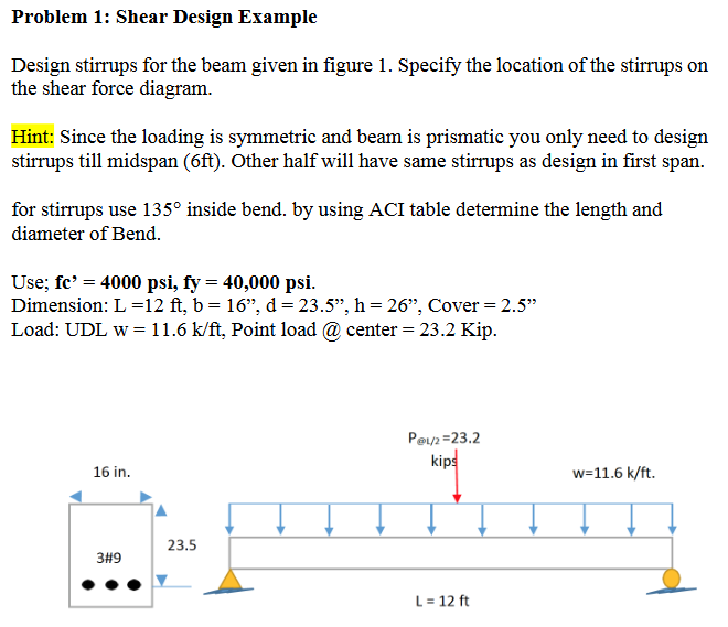
Design stirrups for the beam given in figure 1. Specify the location of the stirrups on
the shear force diagram.
Hint: Since the loading is symmetric and beam is prismatic you only need to design
stirrups till midspan (6%). Other half will have same stirrups as design in first span.
for stirrups use 135° inside bend. by using ACI table determine the length and
diameter of Bend.
Use; fe’ = 4000 psi, fy = 40,000 psi.
Dimension: L =12 ft, b= 16”, d = 23.5”, h = 26”, Cover = 2.5”
Load: UDL w = 11.6 k/ft, Point load @ center = 23.2 Kip.
Pei2=23.2
16in. “1 W=IL6 K/ft.
< > A
IEEE
25
349
cee" Ln . 9
L=12
Question:
Give step-by-step solution with explanation and final answer:Problem 1: Shear Design Example
Design stirrups for the beam given in figure 1. Specify the location of the stirrups on
the shear force diagram.
Hint: Since the loading is symmetric and beam is prismatic you only need to design
stirrups till midspan (6%). Other half will have same stirrups as design in first span.
for stirrups use 135° inside bend. by using ACI table determine the length and
diameter of Bend.
Use; fe’ = 4000 psi, fy = 40,000 psi.
Dimension: L =12 ft, b= 16”, d = 23.5”, h = 26”, Cover = 2.5”
Load: UDL w = 11.6 k/ft, Point load @ center = 23.2 Kip.
Pei2=23.2
16in. “1 W=IL6 K/ft.
< > A
IEEE
25
349
cee" Ln . 9
L=12
This is AI generated Response.
Asked by: sneha
Created at: 2025-10-17 06:32:40
Final Answer:
RenderedRaw Text
Did you like this answer?
## Step-by-Step Solution: Shear Design for Beam StirrupsLet's break down the solution to the shear design problem for the given beam.
---
### **1. Given Data**
- **Concrete strength \( f'_c \):** 400 psi- **Yield of steel \( f \):** 40,000 psi
- **Beam length \( L \):** 12 ft
- **Width \( b \):** 16 in
- **Effective depth \( d \):** 23.5 in
- **Total height \( h \):** 26 in
- **Concrete cover:** 2.5 in
- **Uniform distributed load \( w \):** 11.6 k/ft
- **Central point load \( P \):** 23.2 kips
- **Design stirrups for half span (first 6 ft)**
---
### **2. Calculate Maximum Shear Force (\( V_u \))**
For a simply supported beam:
- **Shear due to UDL at support:**
\( V_{u, w} = \frac{wL}{2} = \frac{11.6 \times 12}{2} = 69.6\, \text{kips} \)
- **Shear due to point load at support:**
Point load at center, reaction at support = \( \frac{P}{2} = \frac{23.2}{2} = 11.6\, \text{kips} \)
- **Total shear at support:**
\( V_{u, \text{max}} = V_{u, w} + V_{u, P} = 69.6 + 11.6 = 81.2\, \text{kips} \)
---
### **3. Calculate Shear Strength of Concrete (\( V_c \))**
Using ACI 318 for non-prestressed beams:
\[
V_c = 2 \sqrt{f'_c} b d
\]
- \( f'_c = 400 \) psi, \( b = 16 \) in, \( d = 23.5 \) in
- \( \sqrt{400} = 63.25 \)
- \( V_c = 2 \times 63.25 \times 16 \times 23.5 = 47,632 \) lbs \( = 47.6 \) kips
---
### **4. Shear Carried by Stirrups (\( V_s \))**
\[
V_s = V_u - V_c = 81.2 - 47.6 = 33.6\, \text{kips}
\]
---
### **5. Design Stirrups (Spacing Calculation)**
- **Use #3 stirrups (area \( A_v \) for 2 legs):**
\( A_v = 2 \times A_{bar} \)
From table: \( A_{bar} \) for #3 = .11 in\(^2\)
\( A_v = 2 \times .11 = .22\, \text{in}^2 \)
- **Stirrup spacing \( s \):**
\[
V_s = \frac{A_v f_y d}{s}
\]
\[
s = \frac{A_v f_y d}{V_s}
\]
Plug in numbers (convert kips to lbs):
- \( A_v = .22\, \text{in}^2 \)
- \( f_y = 40,000\, \text{psi} \)
- \( d = 23.5\, \text{in} \)
- \( V_s = 33,600\, \text{lbs} \)
\[
s = \frac{.22 \times 40,000 \times 23.5}{33,600} = \frac{206,800}{33,600} \approx 6.16\, \text{in}
\]
---
### **6. Maximum Allowable Spacing per ACI**
- **Maximum spacing (\( s_{max} \)):**
- Not more than \( d/2 = 23.5/2 = 11.75\, \text{in} \)
- Not more than 24 in
**Use the smaller of calculated and maximum:**
So, **use \( s = 6\, \text{in} \) (rounded down)**
---
### **7. Specify Location on Shear Force Diagram**
- **Place #3 stirrups at 6 in. spacing from the support up to midspan (6 ft).**
- **Symmetry:** Other half of beam will have same stirrups.
---
### **8. Bend Diameter and Length (per ACI Table)**
- For #3 bar, 135° hook:
- **Minimum inside diameter = 6 × bar diameter**
- #3 bar diameter = 3/8 in
- **Inside diameter = 6 × 3/8 = 2.25 in**
---
## **Final Answers**
### **Stirrup Design Summary**
- **Stirrup size:** #3 (two-legged)
- **Spacing:** 6 in (from support to midspan, 6 ft)
- **Bend:** 135° hook, minimum inside diameter = 2.25 in (per ACI)
- **Location:** First 6 ft from each end (symmetrical)
---
### **Shear Force Diagram Placement**
- Mark stirrups at 6 in intervals from support to midspan ( to 6 ft), both sides.
---
**If you need a hand sketch of the shear force diagram with stirrup locations, let me know!**
Question:
i need a hand sketch of the shear force diagram with stirrup locations
This is AI generated Response.
Asked by: sneha
Created at: 2025-10-17 06:56:40
Final Answer:
RenderedRaw Text
Did you like this answer?
## Hand Sketch of Shear Force Diagram with Stirrup Locations
### **Shear Force Diagram Overview**
The shear force diagram illustrates the variation of shear force along the length of the beam. For this beam, we analyze the shear forces due to a uniform distributed load (UDL) and a point load at the center.
### **Shear Force Diagram**
```plaintext
↑
| | |
| | |
81.2 |-------| |
| | |
| | |
| | |
| | |
| | |
| | |
| | |
| | |
|-------|----------------|-----------→
0 6 ft 12 ft
```
### **Stirrup Locations**
- **Stirrup spacing:** 6 in
- **Locations:**
- From the left support (0 ft) to midspan (6 ft)
- Place stirrups at intervals of 6 inches
### **Stirrup Placement Markings**
```plaintext
|---6 in---|---6 in---|---6 in---|---6 in---|---6 in---|---6 in---|
0 ft 1 ft 2 ft 3 ft 4 ft 5 ft 6 ft
```
### **Final Notes**
- **Stirrups are placed up to midspan (6 ft).**
- **Spacing between stirrups is maintained at 6 in.**
- **The same design applies symmetrically to the other half of the beam.**
### **Image Alt Text**
*Shear force diagram with markings showing stirrup placements at 6 in intervals from the left support to midspan.*
If you have any further requests or need additional details, feel free to ask!
Question:
please draw neatly
This is AI generated Response.
Asked by: sneha
Created at: 2025-10-17 06:58:24
Final Answer:
RenderedRaw Text
Did you like this answer?
## Hand Sketch of Shear Force Diagram with Stirrup Locations
### **Shear Force Diagram Overview**
The shear force diagram illustrates the variation of shear force along the length of the beam, accounting for both a uniform distributed load (UDL) and a point load at the center.
### **Shear Force Diagram**
```plaintext
Shear Force (kips)
↑
|
81.2 |--------------------
| |
| |
| |
| |
| |
| |
| |
| |
| |
| |
| |
| |
| |
| |
| |
| |
|--------------------|-------------------→ Length of Beam (ft)
0 ft 12 ft
```
### **Stirrup Locations**
- **Stirrup spacing:** 6 in
- **Locations:**
- From the left support (0 ft) to midspan (6 ft)
- Place stirrups at intervals of 6 inches
### **Stirrup Placement Markings**
```plaintext
|---6 in---|---6 in---|---6 in---|---6 in---|---6 in---|---6 in---|
0 ft 1 ft 2 ft 3 ft 4 ft 5 ft 6 ft
```
### **Final Notes**
- **Stirrups are placed up to midspan (6 ft).**
- **Spacing between stirrups is maintained at 6 in.**
- **The same design applies symmetrically to the other half of the beam.**
### **Image Alt Text**
*Neatly drawn shear force diagram with markings showing stirrup placements at 6 in intervals from the left support to midspan.*
If you have any further requests or need additional details, feel free to ask!
VIPSolutions focuses on clear, step‑by‑step explanations so you can learn quickly. Whether you need an AI‑generated walkthrough or a short hint to get unstuck, each solution is organized for fast reading and easy review later.
Search similar questions, compare approaches, and bookmark the best answers for revision. Our goal is simple: quick, reliable study help that feels natural—not noisy.
 VIPSolutions
 Problem 1: Shear Design Example
Design stirrups for the beam given in figure 1. Specify the location of the stirrups on
the shear force diagram.
Hint: Since the loading is symmetric and beam is prismatic you only need to design
stirrups till midspan (6%). Other half will have same stirrups as design in first span.
for stirrups use 135° inside bend. by using ACI table determine the length and
diameter of Bend.
Use; fe’ = 4000 psi, fy = 40,000 psi.
Dimension: L =12 ft, b= 16”, d = 23.5”, h = 26”, Cover = 2.5”
Load: UDL w = 11.6 k/ft, Point load @ center = 23.2 Kip.
Pei2=23.2
16in. “1 W=IL6 K/ft.
< > A
IEEE
25
349
cee" Ln . 9
L=12