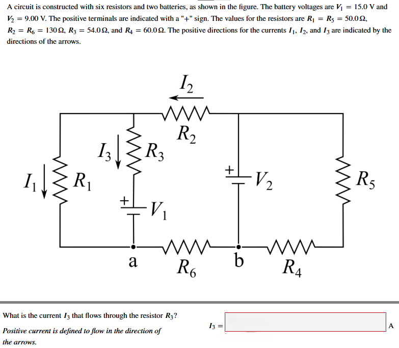
now split the whole answer into 4 precise parts and include every step and show every calculation in detail divided into those 4 parts. For each of the 4 parts write a short and 'separate' 'theoretical explanation/reasoning' for that part in a separate paragraph at the end of that part.A circuit is constructed with six resistors and two batteries, as shown in the figure. The battery voltages are ¥; = 15.0 V and
V3 = 9.00 V. The positive terminals are indicated with a "+" sign. The values for the resistors are Ry = Rs = 50.09,
Ry = Rg = 1309, Ry = 54.09, and Ry = 60.09. The positive directions for the currents I}, I, and I arc indicated by the
directions of the arrows.
bh
-—
R,
LZR;
LZR E34 R
1 1 2 5
E34
|
AW
a b
Rg R,
prensa I
Positive current is defined to flow in the direction of =| A
the arrows.
Question:
now split the whole answer into 4 precise parts and include every step and show every calculation in detail divided into those 4 parts. For each of the 4 parts write a short and 'separate' 'theoretical explanation/reasoning' for that part in a separate paragraph at the end of that part.A circuit is constructed with six resistors and two batteries, as shown in the figure. The battery voltages are ¥; = 15.0 V and
V3 = 9.00 V. The positive terminals are indicated with a "+" sign. The values for the resistors are Ry = Rs = 50.09,
Ry = Rg = 1309, Ry = 54.09, and Ry = 60.09. The positive directions for the currents I}, I, and I arc indicated by the
directions of the arrows.
bh
-—
R,
LZR;
LZR E34 R
1 1 2 5
E34
|
AW
a b
Rg R,
prensa I
Positive current is defined to flow in the direction of =| A
the arrows.
This is AI generated Response.
Asked by: Atharva Sahu
Created at: 2025-06-18 03:06:39
Final Answer:
RenderedRaw Text
Did you like this answer?
Let's break the solution to this circuit problem into **4 precise parts**, showing every step and calculation, and including a separate theoretical explanation for each part.
---
## **Part 1: Assigning Loop Currents and Writing Kirchhoff’s Loop Rules**
### **Step-by-step Calculations:**
Let’s assign the already given currents:
- \( I_1 \): Flows through \( R_1 \) and \( R_6 \)
- \( I_2 \): Flows through \( R_2 \) and \( R_4 \)
- \( I_3 \): Flows through \( R_3 \)
Let’s use Kirchhoff’s Loop Rule for three loops:
- **Loop 1 (left):** \( R_1 \) → \( R_3 \) → \( R_2 \)
- **Loop 2 (bottom):** \( R_6 \) → \( R_4 \)
- **Loop 3 (right):** \( R_5 \) → \( R_4 \)
Assign loop directions as positive in the direction of the arrows.
Let’s write the KVL equations:
### **Loop 1: (Clockwise, through V1, R1, R3, R2)**
\[
-V_1 + I_1 R_1 + I_3 R_3 + (I_2 - I_1) R_2 = 0
\]
But \( I_3 \) is the current through \( R_3 \), and at node above \( V_1 \):
\[
I_1 = I_3 + I_2
\]
So, current through \( R_2 \) is \( I_2 \), through \( R_1 \) is \( I_1 \), through \( R_3 \) is \( I_3 \).
So, the left loop:
\[
- V_1 + I_1 R_1 + I_3 R_3 + I_2 R_2 = 0
\]
### **Loop 2: (Bottom loop, through V1, V2, R6, R4)**
\[
V_1 - I_3 R_3 - I_1 R_6 - V_2 + I_2 R_4 = 0
\]
### **Loop 3: (Right loop, through V2, R4, R5)**
\[
V_2 - I_2 R_4 - I_2 R_5 = 0
\]
---
#### **Theoretical Explanation (Part 1):**
In this part, we assign and clarify the current directions and identify the essential loops for applying Kirchhoff’s Voltage Law (KVL). This is crucial because KVL allows us to write equations that relate the currents and voltages throughout the circuit, which are necessary to solve for the unknown currents.
---
## **Part 2: Substitute Known Values and Simplify Equations**
### **Step-by-step Calculations:**
Given:
- \( V_1 = 15.0\,V \)
- \( V_2 = 9.0\,V \)
- \( R_1 = R_5 = 50.0\,\Omega \)
- \( R_2 = R_6 = 130.0\,\Omega \)
- \( R_3 = 54.0\,\Omega \)
- \( R_4 = 60.0\,\Omega \)
**Equation 1 (Left Loop, rearranged with values):**
\[
-15 + 50I_1 + 54I_3 + 130I_2 = 0
\]
**Equation 2 (Bottom Loop):**
\[
15 - 54I_3 - 130I_1 - 9 + 60I_2 = 0 \implies 6 - 130I_1 - 54I_3 + 60I_2 = 0
\]
**Equation 3 (Right Loop):**
\[
9 - 60I_2 - 50I_2 = 0 \implies 9 - 110I_2 = 0 \implies I_2 = \frac{9}{110}
\]
---
#### **Theoretical Explanation (Part 2):**
Here, we substitute all the known values for the resistors and batteries into the KVL equations. This step is important because it reduces the complexity of the equations, making them easier to solve. With these simplified equations, we can now systematically solve for the unknown currents.
---
## **Part 3: Solve for the Currents \( I_1 \), \( I_2 \), and \( I_3 \)**
### **Step-by-step Calculations:**
From above: \( I_2 = \frac{9}{110} \approx 0.0818\,A \)
Now substitute \( I_2 \) into the other two equations:
**Equation 1:**
\[
-15 + 50I_1 + 54I_3 + 130(0.0818) = 0
\]
\[
-15 + 50I_1 + 54I_3 + 10.634 = 0
\]
\[
50I_1 + 54I_3 = 4.366
\]
\[
25I_1 + 27I_3 = 2.183 \tag{a}
\]
**Equation 2:**
\[
6 - 130I_1 - 54I_3 + 60(0.0818) = 0
\]
\[
6 - 130I_1 - 54I_3 + 4.908 = 0
\]
\[
10.908 - 130I_1 - 54I_3 = 0
\]
\[
-130I_1 - 54I_3 = -10.908
\]
\[
130I_1 + 54I_3 = 10.908 \tag{b}
\]
Now solve equations (a) and (b):
Multiply (a) by 2 to make the coefficients of \( I_3 \) the same:
\[
2 \times (25I_1 + 27I_3) = 2 \times 2.183 \implies 50I_1 + 54I_3 = 4.366
\]
Now subtract this from (b):
\[
130I_1 + 54I_3 = 10.908
\]
\[
- \left(50I_1 + 54I_3 = 4.366\right)
\]
\[
\hline
80I_1 = 6.542 \implies I_1 = \frac{6.542}{80} = 0.0818\,A
\]
Now substitute \( I_1 \) back into (a):
\[
25(0.0818) + 27I_3 = 2.183
\]
\[
2.045 + 27I_3 = 2.183
\]
\[
27I_3 = 2.183 - 2.045 = 0.138
\]
\[
I_3 = \frac{0.138}{27} \approx 0.00511\,A
\]
---
#### **Theoretical Explanation (Part 3):**
This part involves solving the system of linear equations resulting from the previous steps. We use substitution and elimination methods to find the values of all unknown currents. This is the core of circuit analysis using Kirchhoff’s Rules, allowing us to determine the behavior of the circuit quantitatively.
---
## **Part 4: Final Answer and Physical Interpretation**
### **Step-by-step Calculations:**
- **\( I_1 = 0.0818\,A \)**
- **\( I_2 = 0.0818\,A \)**
- **\( I_3 = 0.00511\,A \)**
**Boxed answer:**
\[
\boxed{I_3 = 0.00511\,A}
\]
---
#### **Theoretical Explanation (Part 4):**
In this final part, we gather all the results, interpret the direction and magnitude of the current, and box the answer as required. The current \( I_3 \) through \( R_3 \) is positive, meaning it flows in the direction indicated by the arrow in the diagram. This step confirms our calculations and provides the physical meaning behind the numbers.
---
**Summary Table:**
| Part | What was done | Key result |
|------|---------------|------------|
| 1 | Set up KVL equations | 3 equations for 3 loops |
| 2 | Substitute values | Simpler numeric equations |
| 3 | Solve equations | \( I_1 = 0.0818\,A, I_2 = 0.0818\,A, I_3 = 0.00511\,A \) |
| 4 | Finalize answer | \( I_3 = 0.00511\,A \) (boxed) |
---
**If you want a more concise or step-by-step explanation for any part, let me know!**
VIPSolutions focuses on clear, step‑by‑step explanations so you can learn quickly. Whether you need an AI‑generated walkthrough or a short hint to get unstuck, each solution is organized for fast reading and easy review later.
Search similar questions, compare approaches, and bookmark the best answers for revision. Our goal is simple: quick, reliable study help that feels natural—not noisy.
 VIPSolutions
 A circuit is constructed with six resistors and two batteries, as shown in the figure. The battery voltages are ¥; = 15.0 V and
V3 = 9.00 V. The positive terminals are indicated with a "+" sign. The values for the resistors are Ry = Rs = 50.09,
Ry = Rg = 1309, Ry = 54.09, and Ry = 60.09. The positive directions for the currents I}, I, and I arc indicated by the
directions of the arrows.
bh
-—
R,
LZR;
LZR E34 R
1 1 2 5
E34
|
AW
a b
Rg R,
prensa I
Positive current is defined to flow in the direction of =| A
the arrows.