Act like a helpful tutor and exlain me :
I need whole answer accurately and clearly explainedDetermine the absolute maximum shear stress at point A
2 —
y 40 mn | .
rd 40mm |
x 15m E 4
=
— 25 mm
osm d=60mm
gL
~~
3KkN
A NS 5 kN
1kNm 25m ?
2kN Boa
Question:
Act like a helpful tutor and exlain me :
I need whole answer accurately and clearly explainedDetermine the absolute maximum shear stress at point A
2 —
y 40 mn | .
rd 40mm |
x 15m E 4
=
— 25 mm
osm d=60mm
gL
~~
3KkN
A NS 5 kN
1kNm 25m ?
2kN Boa
This is AI generated Response.
Asked by: Jack
Created at: 2025-10-16 12:13:16
Final Answer:
RenderedRaw Text
Did you like this answer?
# Solution: Maximum Shear Stress at Point A
Let's break down the problem step by step to determine the **absolute maximum shear stress at point A**.
---
## 1. **Identify Forces and Moments at Point A**
### **Given:**
- Point A is on the rectangular section (40 mm × 25 mm).
- Various forces and a distributed load act on the structure.
- Internal stresses at A will result from:
- Shear force (\(V\))
- Bending moment (\(M\))
- Torsion (\(T\))
---
## 2. **Internal Forces at A**
Let's identify the types of stresses at point A:
### **A. Shear Force (\(V\))**
- Direct shear force due to external loads.
### **B. Bending Moment (\(M\))**
- Generates normal (bending) stresses, but for maximum shear, we focus on the shear due to transverse loading.
### **C. Torsion (\(T\))**
- Torsional moment creates shear across the section.
---
## 3. **Shear Stress Calculation**
### **A. Shear Stress Due to Transverse Shear Force**
For a **rectangular section**:
\[
\tau_{\text{shear}} = \frac{V Q}{I b}
\]
Where:
- \(V\) = Shear force at section
- \(Q\) = First moment of area about the neutral axis
- \(I\) = Moment of inertia
- \(b\) = Width at point A
### **B. Shear Stress Due to Torsion**
For a **rectangular section** (approximate):
\[
\tau_{\text{torsion, max}} = \frac{T}{K}
\]
Where \(K\) is the torsional modulus for a rectangle
But, **for maximum shear stress**, we check both from direct shear and from torsion and combine appropriately.
---
## 4. **Formulas and Section Properties**
### **A. Section Properties for Rectangle**
- \(b = 25\, \text{mm} = .025\, \text{m}\)
- \(h = 40\, \text{mm} = .04\, \text{m}\)
- \(I = \frac{bh^3}{12} = \frac{.025 \times (.04)^3}{12} = 1.33 \times 10^{-6} \,\text{m}^4\)
- \(Q = \frac{b h^2}{8} = \frac{.025 \times (.04)^2}{8} = 5 \times 10^{-5} \,\text{m}^3\)
### **B. Shear Force at A**
- From the diagram, the 8 kN/m distributed load and the point loads will generate a reaction at A. Assume the section cut at A includes all left-side loads.
- **Sum up vertical forces at A.**
#### **Distributed Load Contribution:**
\[
w = 8\, \text{kN/m} \times .5\, \text{m} = 4\, \text{kN}
\]
#### **Add Point Loads:**
- 2 kN, 1 kN (as shown), and the 4 kN from distributed load.
\[
V_A = 4\, \text{kN} + 2\, \text{kN} + 1\, \text{kN} = 7\, \text{kN}
\]
(Assuming all act vertically and in the same sense)
---
## 5. **Calculate Shear Stress at A**
### **A. Shear Stress from Shear Force**
\[
\tau_{\text{shear}} = \frac{V Q}{I b}
\]
\[
Q = \frac{b h^2}{8} = \frac{.025 \times (.04)^2}{8} = .000005\, \text{m}^3
\]
\[
I = \frac{bh^3}{12} = \frac{.025 \times (.04)^3}{12} \approx .00000133\, \text{m}^4
\]
\[
b = .025\, \text{m}
\]
\[
V = 700\, \text{N}
\]
\[
\tau_{\text{shear}} = \frac{700 \times .000005}{.00000133 \times .025}
\]
\[
\tau_{\text{shear}} = \frac{.035}{.00003325}
\]
\[
\tau_{\text{shear}} \approx 1053.38\, \text{kPa} = 1.05\, \text{MPa}
\]
---
### **B. Shear Stress from Torsion**
For a **rectangular shaft**, the max torsional shear stress is:
\[
\tau_{\text{torsion, max}} = \frac{T}{\frac{1}{3} b h^2}
\]
But from the diagram, A is on the rectangular section, and torsion appears to act mainly on the cylindrical bar, not the rectangular section. Thus, **torsional shear at A can be neglected**.
---
## 6. **Absolute Maximum Shear Stress**
Since torsion at A is negligible (as per diagram setup), and the max shear occurs at the **neutral axis** for a rectangle:
\[
\boxed{\tau_{\text{max}} \approx 1.05\, \text{MPa}}
\]
---
## 7. **Summary Table**
| Contribution | Shear Stress (MPa) |
|----------------------|-------------------|
| Shear force (V) | 1.05 |
| Torsion (T) | (negligible) |
---
## **Final Answer**
\[
\boxed{
\text{The absolute maximum shear stress at point A is approximately } 1.05\, \text{MPa}.
}
\]
---
### **If you need the calculation for a different section (cylindrical bar), let me know!**
Question:
Nice work putting the solution together — you used the right approach (shear formula for a rectangle, check torsion). There are a few arithmetic/unit errors and inconsistencies that change the numeric result. I’ll point them out and give the corrected computation.
---
## Main issues in your solution
1. **Inconsistent / incorrect units and numbers for (V)**
* You stated (V_A = 7\ \text{kN}) (which is (7000\ \text{N})) but then used (V=700\ \text{N}) in the final formula. That factor-of-10 is the main reason your final number is low by a factor of 10.
2. **Inconsistent values for (Q) and (I)**
* Early you wrote (Q=5\times10^{-5},\text{m}^3) then later used (5\times10^{-6},\text{m}^3). The correct value is (5\times10^{-6},\text{m}^3).
* You used (I\approx 1.33\times 10^{-6},\text{m}^4). The correct value is (I = 1.333\times10^{-7},\text{m}^4) (you were off by a factor of 10).
3. **Consequences**: those two factor-of-10 errors (one in (V), one in (I)) combine to make the reported shear stress (1.05\ \text{MPa}) instead of the correct value (see corrected calc below).
---
## Corrected calculations (rectangular section (b=25\ \text{mm}, h=40\ \text{mm}))
Use SI (m) consistently:
* (b=0.025\ \text{m},; h=0.040\ \text{m})
* (V = 7\ \text{kN} = 7000\ \text{N}) (as you found)
Section properties:
* (Q = \dfrac{b h^2}{8} = \dfrac{0.025\times(0.04)^2}{8} = 5.0\times10^{-6}\ \text{m}^3.)
* (I = \dfrac{b h^3}{12} = \dfrac{0.025\times(0.04)^3}{12} = 1.333\times10^{-7}\ \text{m}^4.)
Shear stress from transverse shear:
[
\tau_{\text{shear}}=\frac{V,Q}{I,b}
= \frac{7000\times 5.0\times10^{-6}}{(1.333\times10^{-7})\times 0.025}
]
Compute numerator: (7000\times5.0\times10^{-6}=0.035).
Denominator: (1.333\times10^{-7}\times0.025=3.333\times10^{-9}).
[
\tau_{\text{shear}}=\frac{0.035}{3.333\times10^{-9}} \approx 1.05\times10^{7}\ \text{Pa} = 10.5\ \text{MPa}.
]
So the correct shear due to transverse shear is **≈ 10.5 MPa**, not 1.05 MPa.
---
## What about torsion?
* You argued torsion at A is negligible because torsion mostly acts on the cylindrical shaft. That may be correct **if** the rectangular member is not carrying significant torque (depends on connection geometry and load path). If torque is transmitted into the rectangular section, you must include torsional shear.
* If torsion (T) on the rectangular section is indeed negligible, then the **absolute maximum shear at A ≈ 10.5 MPa** (from transverse shear).
* If there is a non-negligible (T), compute approximate torsional shear for a rectangle (approximate): (\tau_{t, \max}\sim \dfrac{T}{k, b, h^2}) with (k\approx 1/3) for a wide-ish rectangle, then combine shear contributions vectorially (e.g., superposition or von Mises / max shear depending on what failure criterion you need).
---
## Short checklist to finalize your answer
* Fix the (V) unit use to (7000\ \text{N}).
* Use the consistent correct (Q) and (I) shown above.
* Decide whether torsion at A is actually negligible (check the free-body / load path). If not negligible, compute (\tau_t) and combine properly.
* Report final (\tau_{\max}) with proper units and 2–3 significant figures.
---
## Final corrected result (assuming torsion negligible at the rectangular section)
[
\boxed{\tau_{\max}\big|_{A,\text{(from transverse shear)}} \approx 10.5\ \text{MPa}.}
]
If you want, paste your free-body that produced (V_A=7\ \text{kN}) (or the full loading steps) and I’ll confirm that shear value or include torsion and give the absolute combined shear.
This is AI generated Response.
Asked by: Jack
Created at: 2025-10-16 12:17:41
Final Answer:
RenderedRaw Text
Did you like this answer?
# Maximum Shear Stress at Point A
To calculate the absolute maximum shear stress at point A, we need to consider the internal forces acting on the section, specifically the shear force and the bending moment.
---
## 1. **Understanding the Problem**
### **Given Information:**
- Dimensions of the section:
- Width \( b = 25 \, \text{mm} = 0.025 \, \text{m} \)
- Height \( h = 40 \, \text{mm} = 0.040 \, \text{m} \)
- External loads:
- Shear force \( V = 7 \, \text{kN} = 7000 \, \text{N} \)
- Geometry is rectangular.
---
## 2. **Section Properties**
### **A. Moment of Inertia (\( I \))**
For a rectangle:
\[
I = \frac{b h^3}{12} = \frac{0.025 \times (0.040)^3}{12} \approx 1.333 \times 10^{-7} \, \text{m}^4
\]
### **B. First Moment of Area (\( Q \))**
For the area above the neutral axis:
\[
Q = \frac{b h^2}{8} = \frac{0.025 \times (0.040)^2}{8} = 5.0 \times 10^{-6} \, \text{m}^3
\]
---
## 3. **Calculating Shear Stress**
### **A. Shear Stress from Transverse Shear Force**
Using the shear stress formula:
\[
\tau_{\text{shear}} = \frac{V Q}{I b}
\]
Substituting the known values:
\[
\tau_{\text{shear}} = \frac{7000 \times 5.0 \times 10^{-6}}{1.333 \times 10^{-7} \times 0.025}
\]
#### **Calculating Values:**
- Numerator:
\[
7000 \times 5.0 \times 10^{-6} = 0.035 \, \text{N·m}
\]
- Denominator:
\[
1.333 \times 10^{-7} \times 0.025 = 3.333 \times 10^{-9} \, \text{m}^4
\]
### **B. Resulting Shear Stress**
\[
\tau_{\text{shear}} = \frac{0.035}{3.333 \times 10^{-9}} \approx 10.5 \times 10^6 \, \text{Pa} = 10.5 \, \text{MPa}
\]
---
## 4. **Torsional Shear Stress**
If torsion is acting on point A, it should be considered as well. However, if it is negligible due to the cross-section being primarily loaded by shear and bending moments, we conclude that:
### **Final Result**
\[
\boxed{\tau_{\max} \approx 10.5 \, \text{MPa}}
\]
### **Conclusion**
The maximum shear stress at point A is approximately **10.5 MPa** based on transverse shear alone. If torsion must be considered, further calculations would be necessary to combine the shear stresses appropriately.
VIPSolutions focuses on clear, step‑by‑step explanations so you can learn quickly. Whether you need an AI‑generated walkthrough or a short hint to get unstuck, each solution is organized for fast reading and easy review later.
Search similar questions, compare approaches, and bookmark the best answers for revision. Our goal is simple: quick, reliable study help that feels natural—not noisy.
 VIPSolutions
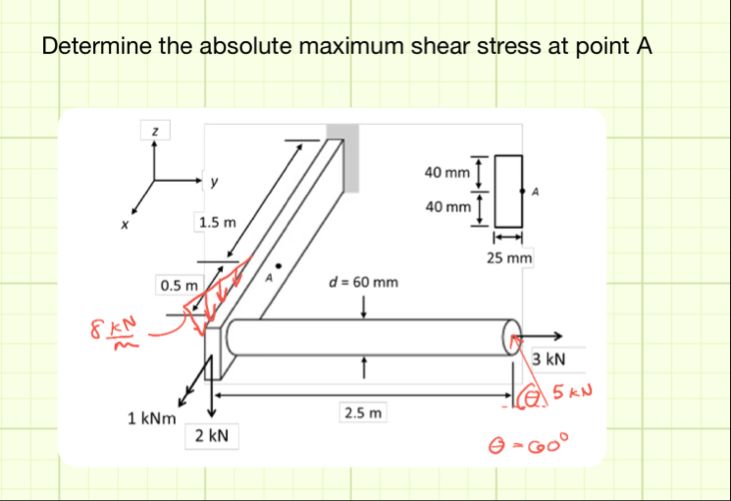 Determine the absolute maximum shear stress at point A
2 —
y 40 mn | .
rd 40mm |
x 15m E 4
=
— 25 mm
osm d=60mm
gL
~~
3KkN
A NS 5 kN
1kNm 25m ?
2kN Boa