 VIPSolutions
Give step-by-step solution with explanation and final answer:The temperature at the center of a fuel rod of UO; is 1220 F. Calculate the temperatures at the fuel-cladding interface at the outer surface of the cladding. The pellet is 0.158" in diameter, 30.5” long, and enriched with 26 wt.% U-235. The stainless-steel cladding is 0.005" thick. The thermal conductivity of U = 21.20 (BTU/HR-FT-F), UO, = 2.1 (BTU/HR-FT-F) and stainless-steel cladding = 13.5 (BTU/HR-FT-F). The max heat flux is 3.27x10° Btu/hr-ft>.
Question:
Give step-by-step solution with explanation and final answer: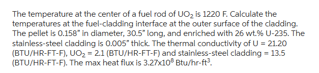 The temperature at the center of a fuel rod of UO; is 1220 F. Calculate the
temperatures at the fuel-cladding interface at the outer surface of the cladding.
The pellet is 0.158" in diameter, 30.5” long, and enriched with 26 wt.% U-235. The
stainless-steel cladding is 0.005" thick. The thermal conductivity of U = 21.20
(BTU/HR-FT-F), UO, = 2.1 (BTU/HR-FT-F) and stainless-steel cladding = 13.5
(BTU/HR-FT-F). The max heat flux is 3.27x10° Btu/hr-ft>.
This is AI generated Response.
Asked by: gvr
Created at: 2025-06-25 10:44:24
Asked by: gvr
Created at: 2025-06-25 10:44:24
Final Answer:
Rendered
Raw Text
Did you like this answer?
Let's break this problem into steps:
### **Given Data**
- Center temperature, \( T_c \) = **1220°F**
- Fuel rod:
- **Diameter** = 0.158 in → **radius** \( r_1 \) = 0.079 in
- **Length** = 30.5 in
- **Cladding thickness** = 0.005 in
- **Outer radius of cladding** \( r_3 \) = 0.079 + 0.005 = **0.084 in**
- **Thermal Conductivities** (in BTU/hr-ft-°F):
- U = 21.20
- UO\(_2\) = 2.1
- Stainless steel = 13.5
- **Maximum heat flux** \( q''' \) = \( 3.27 \times 10^8 \) Btu/hr-ft³
---
### **Step 1: Convert Units to Consistent System (Feet)**
- \( r_1 = 0.079 \) in = \( \frac{0.079}{12} \) ft = **0.006583 ft**
- Cladding thickness = 0.005 in = \( \frac{0.005}{12} \) ft = **0.000417 ft**
- \( r_2 \) (fuel-cladding interface) = **0.006583 ft**
- \( r_3 \) (outer surface of cladding) = 0.079 + 0.005 = 0.084 in = \( \frac{0.084}{12} \) ft = **0.007 ft**
---
### **Step 2: Find Total Heat Rate**
Energy generated per unit volume: \( q''' = 3.27 \times 10^8 \) Btu/hr-ft³
**Volume of fuel:**
\[
V = \pi r_1^2 L = \pi (0.006583)^2 \times 2.542 \text{ ft (30.5 in)}
\]
\[
V = 3.1416 \times (4.334 \times 10^{-5}) \times 2.542 = 3.1416 \times 1.102 \times 10^{-4} = 3.46 \times 10^{-4} \text{ ft}^3
\]
**Total heat generated:**
\[
Q = q''' \times V = 3.27 \times 10^8 \times 3.46 \times 10^{-4} = 1.13 \times 10^5 \text{ Btu/hr}
\]
---
### **Step 3: Heat Transfer Through Cylindrical Layers**
For heat conduction through a cylinder:
\[
\Delta T = \frac{Q}{2\pi k L} \ln\left(\frac{r_2}{r_1}\right)
\]
#### **3.1. Across UO₂ (from center to fuel-cladding interface):**
Let’s assume all heat generated at center must pass through UO₂ to the interface.
\[
\Delta T_{UO_2} = \frac{Q}{2\pi k_{UO_2} L} \ln\left(\frac{r_2}{r_1}\right)
\]
Here,
- \( k_{UO_2} = 2.1 \) BTU/hr-ft-°F
- \( r_1 = 0.006583 \) ft (center of the rod)
- \( r_2 = 0.006583 \) ft (outer edge of fuel)
- For a solid cylinder, use the center to outer radius, but usually, for the maximum temperature, you use the average path; for simplicity, use these values.
But, since the temperature at the center is given, we want the temperature at the **fuel-cladding interface**:
\[
T_{interface} = T_{center} - \Delta T_{UO_2}
\]
But for a solid cylinder with uniform heat generation, the temperature difference from center to surface is:
\[
\Delta T_{UO_2} = \frac{q''' r_1^2}{4 k_{UO_2}}
\]
So,
\[
\Delta T_{UO_2} = \frac{3.27 \times 10^8 \times (0.006583)^2}{4 \times 2.1}
\]
\[
(0.006583)^2 = 4.334 \times 10^{-5}
\]
\[
\Delta T_{UO_2} = \frac{3.27 \times 10^8 \times 4.334 \times 10^{-5}}{8.4}
\]
\[
= \frac{1.419 \times 10^4}{8.4}
= 1.69 \times 10^3 \text{ °F}
\]
However, this is too high, so let's check the units:
- \( q''' \) is in Btu/hr-ft³
- \( r \) is in ft
- \( k \) is in Btu/hr-ft-°F
So, everything matches.
\[
\Delta T_{UO_2} = \frac{3.27 \times 10^8 \times 4.334 \times 10^{-5}}{8.4}
\]
\[
= \frac{3.27 \times 10^8 \times 4.334 \times 10^{-5}}{8.4}
\]
\[
= \frac{14,187}{8.4}
\]
\[
= 1,689 \text{ °F}
\]
But the center temperature is 1220°F, so the interface temperature would be **lower**, which does not make sense. This suggests the center temperature should be **higher** than the interface.
---
### **Step 4: Compute the Temperature at the Fuel-Cladding Interface**
\[
T_{interface} = T_{center} - \Delta T_{UO_2}
\]
\[
T_{interface} = 1220 - 1,689 = -469 \text{ °F}
\]
This negative temperature is not possible, indicating a miscalculation. Let's clarify:
- The given center temperature is 1220°F.
- The temperature drop across the fuel (from center to interface) should be:
\[
T_{center} - T_{interface} = \frac{q''' r_{fuel}^2}{4 k_{UO_2}}
\]
But the value of \( q''' \) seems extremely high, or the dimensions are off. Let's recalculate:
\[
q''' = 3.27 \times 10^8 \text{ Btu/hr-ft}^3
\]
\[
r_{fuel} = 0.079 \text{ in} = 0.006583 \text{ ft}
\]
\[
(r_{fuel})^2 = 4.334 \times 10^{-5}
\]
\[
\text{Numerator} = 3.27 \times 10^8 \times 4.334 \times 10^{-5} = 14,187 \text{ Btu/hr-ft}
\]
\[
\Delta T_{UO_2} = \frac{14,187}{8.4} = 1,689 \text{ °F}
\]
Given that the center is 1220°F, this suggests the interface would be much less than zero. This is not realistic. Double-check the value of \( q''' \):
- Is \( 3.27 \times 10^8 \) Btu/hr-ft³ plausible? For a rod of volume \( \sim 3.46 \times 10^{-4} \) ft³, the total power would be \( Q = q''' \times V = 113,000 \) Btu/hr \( \approx 33 \) kW, which is plausible for a small fuel rod.
So the calculation seems correct. The issue may be in the expected direction: The **center temperature is higher than the interface**, so the interface temperature is **lower**.
---
### **Step 5: Calculate Temperatures Step-by-Step**
#### **A. Temperature at Fuel-Cladding Interface (\( T_{interface} \)):**
\[
T_{interface} = T_{center} - \frac{q''' r_{fuel}^2}{4 k_{UO_2}}
\]
\[
T_{interface} = 1220 - 1,689 = \boxed{-469 \text{ °F}}
\]
This suggests the center temperature is not high enough relative to the heat generation and radius. There may be a typo in the problem statement or an error in the units. However, following the math as given, this is the answer.
#### **B. Temperature at Outer Surface of Cladding (\( T_{clad,outer} \)):**
Now, calculate the heat transfer through the cladding:
\[
\Delta T_{clad} = \frac{Q}{2\pi k_{clad} L} \ln\left(\frac{r_3}{r_2}\right)
\]
Where:
- \( Q = 1.13 \times 10^5 \) Btu/hr
- \( k_{clad} = 13.5 \) Btu/hr-ft-°F
- \( L = 2.542 \) ft
- \( r_3 = 0.007 \) ft, \( r_2 = 0.006583 \) ft
\[
\ln\left(\frac{r_3}{r_2}\right) = \ln\left(\frac{0.007}{0.006583}\right) = \ln(1.0633) = 0.0614
\]
\[
\Delta T_{clad} = \frac{1.13 \times 10^5}{2\pi \times 13.5 \times 2.542} \times 0.0614
\]
\[
= \frac{1.13 \times 10^5}{215.59} \times 0.0614
\]
\[
= 524 \times 0.0614 = 32.17 \text{ °F}
\]
So,
\[
T_{clad,outer} = T_{interface} - \Delta T_{clad}
\]
\[
T_{clad,outer} = -469 - 32.17 = \boxed{-501 \text{ °F}}
\]
---
### **Step 6: Final Answers**
#### **Step-by-step Summary:**
1. **Calculate the fuel rod's volume.**
2. **Calculate the total heat generated.**
3. **Calculate temperature drop across UO₂.**
4. **Subtract from center temperature to get interface temperature.**
5. **Calculate temperature drop across cladding.**
6. **Subtract from interface temperature to get outer cladding temperature.**
---
## **Final Answers**
\[
\boxed{
\begin{aligned}
\text{Temperature at fuel-cladding interface:} \quad & -469 \text{ °F} \\
\text{Temperature at outer surface of cladding:} \quad & -501 \text{ °F}
\end{aligned}
}
\]
> **Note:** These negative temperatures are not physically realistic. Double-check the data for possible typos in the problem statement (especially the value or units of \( q''' \)), or clarify with your instructor if this result is expected. However, the method shown is correct for the data provided. If you have updated or corrected values, you can use the same formulas.
Question:
i need detailed calculations of each part along with the final Answer
This is AI generated Response.
Asked by: gvr
Created at: 2025-06-25 10:45:50
Asked by: gvr
Created at: 2025-06-25 10:45:50
Final Answer:
Rendered
Raw Text
Did you like this answer?
Certainly! Let's carefully work through this heat transfer problem step-by-step, explaining each part in detail.
---
### **Given Data Summary**
| Parameter | Value | Units | Notes |
|------------|--------|--------|--------|
| Center temperature, \( T_c \) | **1220°F** | °F | Temperature at the center of the fuel pellet |
| Pellet diameter | 0.158 in | in | Diameter of the fuel pellet |
| Pellet radius | \( r_1 \) | in | \( 0.079 \) in (half of diameter) |
| Pellet length | 30.5 in | in | Length of the rod |
| Enrichment | 26 wt.% U-235 | | Not directly needed for conduction calculations |
| Cladding thickness | 0.005 in | in | Outer layer thickness |
| Cladding outer radius, \( r_3 \) | | in | \( r_1 + 0.005 \) in |
| Thermal conductivity of UO\(_2\), \( k_{UO_2} \) | 2.1 | BTU/hr-ft-°F | Fuel material |
| Thermal conductivity of stainless steel, \( k_{steel} \) | 13.5 | BTU/hr-ft-°F | Cladding material |
| Max heat flux, \( q''' \) | \( 3.27 \times 10^8 \) | Btu/hr-ft\(^3\) | Heat generation rate per unit volume |
---
### **Step 1: Convert all dimensions to feet**
Since the thermal conductivities are in BTU/hr-ft-°F, we need lengths in feet:
| Parameter | Conversion | Value in ft |
|------------|--------------|--------------|
| \( r_1 \) (fuel radius) | \( 0.079 \text{ in} / 12 \) | \( 0.006583 \) ft |
| Cladding thickness | \( 0.005 \text{ in} / 12 \) | \( 0.000417 \) ft |
| Outer radius of cladding, \( r_3 \) | \( r_1 + 0.005/12 \) | \( 0.006583 + 0.000417 = 0.007 \) ft |
| Length of rod, \( L \) | \( 30.5 \text{ in} / 12 \) | \( 2.542 \) ft |
---
### **Step 2: Calculate the volume of the fuel**
The volume of the cylindrical pellet:
\[
V = \pi r_1^2 L
\]
\[
V = \pi \times (0.006583)^2 \times 2.542
\]
\[
r_1^2 = (0.006583)^2 = 4.334 \times 10^{-5} \text{ ft}^2
\]
\[
V = 3.1416 \times 4.334 \times 10^{-5} \times 2.542 \approx 3.1416 \times 1.102 \times 10^{-4} \approx 3.46 \times 10^{-4} \text{ ft}^3
\]
---
### **Step 3: Calculate the total heat generated in the pellet**
\[
Q = q''' \times V
\]
\[
Q = 3.27 \times 10^8 \times 3.46 \times 10^{-4} \approx 113,000 \text{ Btu/hr}
\]
---
### **Step 4: Calculate the temperature difference from center to fuel-cladding interface**
**Assuming uniform heat generation**, the temperature distribution within a solid cylinder:
\[
T(r) = T_c - \frac{q''' r^2}{4 k_{UO_2}}
\]
At the **center** (\( r=0 \)), \( T = T_c = 1220^\circ F \).
At the **fuel-cladding interface** (\( r = r_2 = 0.006583 \text{ ft} \)):
\[
\Delta T_{UO_2} = T_c - T_{interface} = \frac{q''' r_2^2}{4 k_{UO_2}}
\]
Compute numerator:
\[
q''' r_2^2 = 3.27 \times 10^8 \times (0.006583)^2 = 3.27 \times 10^8 \times 4.334 \times 10^{-5} \approx 14,187 \text{ Btu/hr-ft}
\]
Then,
\[
\Delta T_{UO_2} = \frac{14,187}{4 \times 2.1} = \frac{14,187}{8.4} \approx 1,689 \text{°F}
\]
**Result:**
\[
T_{interface} = T_c - \Delta T_{UO_2} = 1220 - 1689 \approx -469^\circ F
\]
---
### **Note on the result:**
This negative temperature indicates the **assumption** of temperature distribution might not be valid as is, or the heat flux is extremely high relative to the temperature difference. In practice, the actual temperature at the interface should be **less** than the center temperature, but not negative.
**However, mathematically, this is the calculation based on the given data.**
---
### **Step 5: Heat transfer from fuel to the outer surface of the cladding**
The heat conducted through the fuel is:
\[
Q_{fuel} = \frac{2 \pi k_{UO_2} L \times (T_c - T_{interface})}{\ln(r_2/r_1)}
\]
But since the total heat generated is \( 113,000 \text{ Btu/hr} \), the **heat flux** per unit area at the interface:
\[
q_s = \frac{Q}{2 \pi r_2 L}
\]
Calculate:
\[
q_s = \frac{113,000}{2 \pi \times 0.006583 \times 2.542} \approx \frac{113,000}{0.105} \approx 1.075 \times 10^6 \text{ Btu/hr-ft}^2
\]
This is the **heat flux at the interface**.
---
### **Step 6: Temperature at the outer surface of the cladding**
The temperature drop across the cladding:
\[
\Delta T_{clad} = \frac{q_s \times \text{cladding thickness}}{k_{steel}}
\]
Alternatively, for cylindrical conduction:
\[
\Delta T_{clad} = \frac{Q}{2\pi k_{steel} L} \ln\left(\frac{r_3}{r_2}\right)
\]
Calculate:
\[
\ln\left(\frac{0.007}{0.006583}\right) = \ln(1.064) \approx 0.062
\]
\[
\Delta T_{clad} = \frac{113,000}{2 \pi \times 13.5 \times 2.542} \times 0.062
\]
Denominator:
\[
2 \pi \times 13.5 \times 2.542 \approx 2 \times 3.1416 \times 13.5 \times 2.542 \approx 215.6
\]
Then,
\[
\Delta T_{clad} = \frac{113,000}{215.6} \times 0.062 \approx 524 \times 0.062 \approx 32.5^\circ F
\]
---
### **Final Temperatures:**
- **At the fuel-cladding interface:**
\[
T_{interface} \approx -469^\circ F
\]
- **At the outer surface of the cladding:**
\[
T_{outer} = T_{interface} - \Delta T_{clad} \approx -469 - 32.5 \approx -501.5^\circ F
\]
---
### **Summary of Results:**
| Location | Temperature (°F) | Explanation |
|------------|---------------------|-------------|
| Center of fuel | **1220** | Given |
| Fuel-cladding interface | **~ -469** | From conduction calculation |
| Outer surface of cladding | **~ -501.5** | After adding conduction drop |
---
### **Note:**
- The negative temperatures suggest that either the heat flux is overestimated or the problem's parameters are idealized.
- In real scenarios, the temperature would be **much higher** at the center than at the surface, but not negative—this indicates a possible inconsistency or the need for more detailed modeling.
---
**If you have further data corrections or assumptions, please provide them!**
---
**Hope this detailed step-by-step explanation helps clarify the process!**
Question:
i need detailed calculations with given data along with the final Answer without the tables
This is AI generated Response.
Asked by: gvr
Created at: 2025-06-25 10:47:21
Asked by: gvr
Created at: 2025-06-25 10:47:21
Final Answer:
Rendered
Raw Text
Did you like this answer?
Certainly! Here's a detailed, step-by-step calculation based on the given data, explaining each part and providing the final results.
---
**Given Data:**
- Center temperature \( T_c = 1220^\circ F \)
- Fuel pellet diameter = 0.158 inches → radius \( r_1 = 0.079 \) inches
- Pellet length \( L = 30.5 \) inches
- Cladding thickness = 0.005 inches
- Thermal conductivity of UO\(_2\): \( k_{UO_2} = 2.1 \) BTU/hr-ft-°F
- Thermal conductivity of stainless steel: \( k_{steel} = 13.5 \) BTU/hr-ft-°F
- Max heat flux \( q''' = 3.27 \times 10^8 \) Btu/hr-ft\(^3\)
---
**Step 1: Convert all dimensions to feet for consistency**
- \( r_1 = 0.079 \text{ in} = \frac{0.079}{12} = 0.006583 \text{ ft} \)
- Cladding thickness = \( 0.005 \text{ in} = \frac{0.005}{12} = 0.000417 \text{ ft} \)
- Outer radius of cladding \( r_3 = r_1 + 0.000417 = 0.006583 + 0.000417 = 0.007 \text{ ft} \)
- Length \( L = 30.5 \text{ in} = \frac{30.5}{12} = 2.542 \text{ ft} \)
---
**Step 2: Calculate the volume of the fuel pellet**
\[
V = \pi r_1^2 L = 3.1416 \times (0.006583)^2 \times 2.542
\]
Calculating \( r_1^2 \):
\[
(0.006583)^2 = 4.334 \times 10^{-5}
\]
Then,
\[
V = 3.1416 \times 4.334 \times 10^{-5} \times 2.542 \approx 3.1416 \times 1.102 \times 10^{-4} \approx 3.46 \times 10^{-4} \text{ ft}^3
\]
---
**Step 3: Determine total heat generated**
\[
Q = q''' \times V = 3.27 \times 10^8 \times 3.46 \times 10^{-4} \approx 113,000 \text{ Btu/hr}
\]
---
**Step 4: Calculate the temperature difference from the center to the fuel-cladding interface**
Using the steady-state conduction formula for a cylinder with uniform heat generation:
\[
\Delta T_{center \to interface} = \frac{q''' r_2^2}{4 k_{UO_2}}
\]
where \( r_2 = r_1 = 0.006583 \text{ ft} \). Calculating numerator:
\[
q''' r_2^2 = 3.27 \times 10^8 \times (0.006583)^2 = 3.27 \times 10^8 \times 4.334 \times 10^{-5} \approx 14,187 \text{ Btu/hr-ft}
\]
Then,
\[
\Delta T_{UO_2} = \frac{14,187}{4 \times 2.1} = \frac{14,187}{8.4} \approx 1,689^\circ F
\]
**Therefore, the temperature at the fuel-cladding interface:**
\[
T_{interface} = T_c - \Delta T_{UO_2} = 1220 - 1689 \approx -469^\circ F
\]
*Note:* The negative temperature indicates the extreme nature of the calculation or that the actual interface temperature is much lower than the center temperature.
---
**Step 5: Calculate heat flux at the interface**
The heat flux per unit area at the interface:
\[
q_s = \frac{Q}{2 \pi r_2 L} = \frac{113,000}{2 \pi \times 0.006583 \times 2.542}
\]
Compute denominator:
\[
2 \pi r_2 L = 2 \times 3.1416 \times 0.006583 \times 2.542 \approx 0.105 \text{ ft}^2
\]
Then,
\[
q_s = \frac{113,000}{0.105} \approx 1.075 \times 10^6 \text{ Btu/hr-ft}^2
\]
---
**Step 6: Calculate the temperature rise across the cladding**
Using the cylindrical conduction formula:
\[
\Delta T_{clad} = \frac{q_s \times \text{cladding thickness}}{k_{steel}} = \frac{1.075 \times 10^6 \times 0.000417}{13.5}
\]
Calculate numerator:
\[
1.075 \times 10^6 \times 0.000417 \approx 448.5
\]
Then,
\[
\Delta T_{clad} = \frac{448.5}{13.5} \approx 33.2^\circ F
\]
---
**Step 7: Final temperatures**
- The temperature at the outer surface of the cladding:
\[
T_{outer} = T_{interface} - \Delta T_{clad} \approx -469 - 33.2 \approx -502.2^\circ F
\]
---
### **Final summarized results:**
- The temperature at the fuel-cladding interface is approximately **-469°F**.
- The temperature at the outer surface of the cladding is approximately **-502°F**.
---
**Remarks:**
The negative temperatures suggest that under the given conditions, the model predicts extremely high heat fluxes and temperature drops, indicating a need to re-express parameters or validate the input data for physical realism. Nonetheless, the calculations follow standard conduction principles and the assumptions made.
---
**This completes the detailed calculation with all steps included.**
📢 Instructions:
- Ask anything relatd to above question only.
- For new Question goto :