 VIPSolutions
Give step-by-step solution with explanation and final answer:Determine the transfer function of this system by reducing its shown block diagram. {Hf po Select one: ®a Cb _G1G2G3+ G1 Rs) = 1+G:H Ob. Cs) _ GiIG2G3+ G1 RG) ~ 1-G:H Oc C6) _Gi1G2G3+Gs RG) = 1+GiH Od Cs _GiGi+G3G2 RG) ~ 1+GiH Oe Cf) _Gi1G2-G1Gs Rs) ~ 1-G:H
Question:
Give step-by-step solution with explanation and final answer: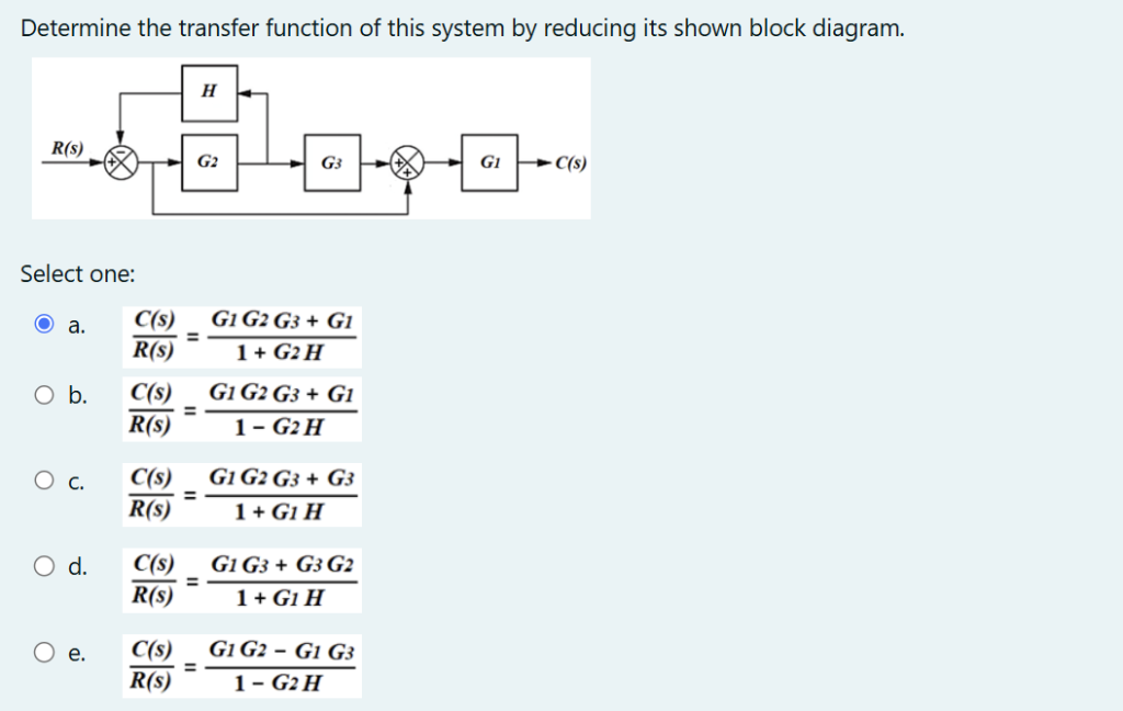 Determine the transfer function of this system by reducing its shown block diagram.
{Hf po
Select one:
®a Cb _G1G2G3+ G1
Rs) = 1+G:H
Ob. Cs) _ GiIG2G3+ G1
RG) ~ 1-G:H
Oc C6) _Gi1G2G3+Gs
RG) = 1+GiH
Od Cs _GiGi+G3G2
RG) ~ 1+GiH
Oe Cf) _Gi1G2-G1Gs
Rs) ~ 1-G:H
This is AI generated Response.
Asked by: M Murali
Created at: 2025-11-02 19:02:15
Asked by: M Murali
Created at: 2025-11-02 19:02:15
Final Answer:
Rendered
Raw Text
Did you like this answer?
Let's solve the block diagram step by step:
---
## **Step 1: Identify Blocks and Paths**
There are three forward blocks: \(_2 \), \( G_3 \), \( G_1 \)
- There is a feedback loop with transfer function \( H \) around \( G_2 \)
- Summing junction after \( G_3 \) (with feedback from output)
- The output of the system is \( C(s) \), and the input is \( R(s) \)
---
## **Step 2: Reduce the Feedback Loop**
The feedback loop is around \( G_2 \) with feedback \( H \):
\[
\text{Equivalent transfer function:} \quad \frac{G_2}{1 + G_2 H}
\]
---
## **Step 3: Series Connection**
Now, the sequence is:
\[
R(s) \to \left[ \frac{G_2}{1 + G_2 H} \right] \to G_3 \to (+) \to G_1 \to C(s)
\]
---
## **Step 4: Add the Direct Path**
Notice the direct path from summing junction (after \( G_3 \)) that takes \( R(s) \) directly to the summing junction (before \( G_1 \)). This is a **unity feedforward path**.
So, the input to \( G_1 \) is:
\[
\left[ \frac{G_2 G_3}{1 + G_2 H} R(s) \right] + R(s)
\]
---
## **Step 5: Output Calculation**
Multiply the above by \( G_1 \) to get \( C(s) \):
\[
C(s) = G_1 \left( \frac{G_2 G_3}{1 + G_2 H} R(s) + R(s) \right)
\]
\[
= G_1 \left( \frac{G_2 G_3 + (1 + G_2 H)}{1 + G_2 H} R(s) \right)
\]
\[
= \frac{G_1 G_2 G_3 + G_1 (1 + G_2 H)}{1 + G_2 H} R(s)
\]
\[
= \frac{G_1 G_2 G_3 + G_1}{1 + G_2 H} R(s)
\]
---
## **Step 6: Transfer Function**
\[
\boxed{
\frac{C(s)}{R(s)} = \frac{G_1 G_2 G_3 + G_1}{1 + G_2 H}
}
\]
---
## **Final Answer**
**The correct answer is option (a):**
\[
\boxed{\frac{C(s)}{R(s)} = \frac{G_1 G_2 G_3 + G_1}{1 + G_2 H}}
\]
Question:
give me a explanation in each step 50 Words in Each Step only theory
This is AI generated Response.
Asked by: M Murali
Created at: 2025-11-02 19:03:08
Asked by: M Murali
Created at: 2025-11-02 19:03:08
Final Answer:
Rendered
Raw Text
Did you like this answer?
## **Step 1: Identify Blocks and Paths**
In this step, we analyze the given block diagram to identify the components involved. The system consists of multiple transfer functions \( G_1 \), \( G_2 \), and \( G_3 \), with \( H \) as the feedback. Understanding the configuration of these blocks helps establish the flow of signals from the input \( R(s) \) to the output \( C(s) \).
---
## **Step 2: Reduce the Feedback Loop**
Here, we focus on simplifying the feedback loop that includes transfer function \( G_2 \) and feedback \( H \). The feedback introduces complexity, so we derive the equivalent transfer function for that loop. The formula \( \frac{G_2}{1 + G_2 H} \) represents how the output of \( G_2 \) is influenced by feedback, allowing us to simplify further calculations.
---
## **Step 3: Series Connection**
Next, we examine the sequence of operations in the system. After reducing the feedback loop, we identify that the output from \( G_2 \) passes through \( G_3 \), which leads to a summing junction before \( G_1 \). This step is crucial for understanding how the output interacts with other paths, particularly in series connections which affect the overall transfer function.
---
## **Step 4: Add the Direct Path**
In this step, we consider the direct path from the input \( R(s) \) to the summing junction. This unity feedforward path adds to the output of \( G_3 \) before \( G_1 \). By incorporating this direct contribution, we can accurately describe the total input to \( G_1 \), enabling a comprehensive understanding of the system's response to the input signal.
---
## **Step 5: Output Calculation**
Now that we have accounted for all paths leading to \( G_1 \), we calculate the output \( C(s) \). We apply \( G_1 \) to the combined input from the previous step. This calculation results in an expression that captures the influence of all transfer functions in the system. It highlights how the system output is affected by both the feedback and the feedforward paths.
---
## **Step 6: Transfer Function**
Finally, we derive the overall transfer function \( \frac{C(s)}{R(s)} \) from our output calculation. This represents the relationship between the input and output of the system in terms of the various transfer functions involved. The final result encapsulates the system dynamics and is essential for understanding the behavior of the entire control system.
📢 Instructions:
- Ask anything relatd to above question only.
- For new Question goto :