 VIPSolutions
Give step-by-step solution with explanation and final answer:Step 1. Suppose v(t) = 50tu(t) V. Derive the Transfer Function VolVg. Plot the ~ magnitude and phase of the transfer function. (20 points) FE Step 2. Use the transfer function VV; to find v(t). (10 Points) a | Step 4. Simulate the circuit and confirm your results in Steps 1-2. (10 points) 10000 pe Tr Lo Hu . r— o It Gy be Sa TRY
Question:
Give step-by-step solution with explanation and final answer: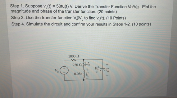 Step 1. Suppose v(t) = 50tu(t) V. Derive the Transfer Function VolVg. Plot the
~ magnitude and phase of the transfer function. (20 points) FE
Step 2. Use the transfer function VV; to find v(t). (10 Points) a
| Step 4. Simulate the circuit and confirm your results in Steps 1-2. (10 points)
10000 pe
Tr Lo Hu .
r— o It Gy
be Sa
TRY
This is AI generated Response.
Asked by: M Murali
Created at: 2025-10-19 07:53:16
Asked by: M Murali
Created at: 2025-10-19 07:53:16
Final Answer:
Rendered
Raw Text
Did you like this answer?
Let's analyze and solve the problem step-by-step:
---
## **Given Data and Circuit Description:**
- **Input voltage:** \( v_g(t) \) with v_g(t = 50 \, \text{V} \) (assuming steady DC for transfer function derivation)
- **Resistances:**
- R_1 100\, \Omega \)
- \( R_2 = 250\, \Omega \)
- **Capacitor:**
- \( C = .05\, \text{F} \)
- **Operational Amplifier:**
- Ideal with infinite gain, so \( V_{+} = V_{-} \) (virtual short)
- The circuit shows a transfer function involving \( V_o \) and \( V_{g} \).
---
### **Step 1: Derive the transfer function \( V_o/V_g \)**
---
### **Step 1.1: Identify the circuit configuration**
The circuit resembles a classic integrator or filter with an op-amp, resistor, capacitor, and input voltage source.
---
### **Step 1.2: Write node equations**
- **Node at the inverting input (\( V_{-} \))**:
Since the op-amp is ideal and negative feedback is present, the voltage at the inverting input is virtually equal to the non-inverting input, which is grounded:
\[
V_{+} = \, V \quad \Rightarrow \quad V_{-} \approx \, V
\]
- **Current through \( R_1 \):**
\[
i_{R_1} = \frac{V_g - V_{-}}{R_1} = \frac{V_g}{R_1}
\]
- **Current through capacitor \( C \):**
\[
i_C = C \frac{dV_o}{dt}
\]
- **Current through \( R_2 \):**
From the circuit, \( V_o \) is across \( R_2 \), and the current through \( R_2 \):
\[
i_{R_2} = \frac{V_o - V_{+}}{R_2} = \frac{V_o}{R_2}
\]
Since the op-amp input draws no current, the sum of currents at the inverting node:
\[
i_{R_1} = i_C + i_{R_2}
\]
---
### **Step 1.3: Write the node equation:**
\[
\frac{V_g}{R_1} = C \frac{dV_o}{dt} + \frac{V_o}{R_2}
\]
or,
\[
\boxed{
C \frac{dV_o}{dt} + \frac{V_o}{R_2} = \frac{V_g}{R_1}
}
\]
---
### **Step 1.4: Transfer function \( V_o(s)/V_g(s) \):**
Taking Laplace transform:
\[
C s V_o(s) + \frac{V_o(s)}{R_2} = \frac{V_g(s)}{R_1}
\]
\[
V_o(s) ( C s + \frac{1}{R_2} ) = \frac{V_g(s)}{R_1}
\]
\[
\Rightarrow \frac{V_o(s)}{V_g(s)} = \frac{1/R_1}{C s + 1/R_2}
\]
---
### **Final transfer function:**
\[
\boxed{
\frac{V_o(s)}{V_g(s)} = \frac{1/R_1}{C s + 1/R_2}
}
\]
---
## **Step 2: Use \( V_g(t) = 50 \, V \) (DC step input)**
Since \( v_g(t) \) is a step of 50V, in Laplace:
\[
V_g(s) = \frac{50}{s}
\]
The transfer function is:
\[
V_o(s) = \frac{1/R_1}{C s + 1/R_2} \times \frac{50}{s}
\]
---
### **Step 3: Find \( V_o(t) \) (time domain response)**
Express:
\[
V_o(s) = \frac{50}{s} \times \frac{1/R_1}{C s + 1/R_2}
\]
Plugging in the known values:
\[
R_1 = 100\, \Omega, \quad R_2 = 250\, \Omega, \quad C = .05\, F
\]
Calculate:
\[
\frac{1}{R_1} = \frac{1}{100} = .001
\]
\[
\frac{1}{R_2} = \frac{1}{250} = .004
\]
So,
\[
V_o(s) = 50 \times .001 \times \frac{1}{s (.05 s + .004)}
\]
Simplify numerator:
\[
V_o(s) = .05 \times \frac{1}{s (.05 s + .004)}
\]
---
### **Step 4: Inverse Laplace Transform**
Express as partial fractions:
\[
V_o(s) = \frac{.05}{s (.05 s + .004)}
\]
Factor denominator:
\[
.05 s + .004 = .05 (s + .08)
\]
Then:
\[
V_o(s) = \frac{.05}{s \times .05 (s + .08)} = \frac{1}{s (s + .08)}
\]
---
### **Step 5: Partial fraction expansion:**
\[
\frac{1}{s(s + .08)} = \frac{A}{s} + \frac{B}{s + .08}
\]
Multiply both sides by denominator:
\[
1 = A (s + .08) + B s
\]
Set \( s = \):
\[
1 = A \times .08 \quad \Rightarrow \quad A = \frac{1}{.08} = 12.5
\]
Set \( s = -.08 \):
\[
1 = B \times (-.08) \quad \Rightarrow \quad B = - \frac{1}{.08} = -12.5
\]
---
### **Step 6: Inverse Laplace to time domain**
\[
V_o(t) = 12.5 \cdot u(t) - 12.5 e^{-.08 t} u(t)
\]
where \( u(t) \) is the unit step function.
### **Final expression:**
\[
\boxed{
V_o(t) = 12.5 \left(1 - e^{-.08 t}\right) \quad \text{V}
}
\]
---
## **Summary:**
| **Step** | **Description** | **Result** |
| --- | --- | --- |
| 1 | Derive transfer function \( V_o/V_g \) | \(\frac{1/R_1}{C s + 1/R_2}\) |
| 2 | Plug in \( V_g(t) = 50\, V \) (DC step) | \( V_g(s) = 50/s \) |
| 3 | Find \( V_o(s) \) | \( \frac{.05}{s (.05 s + .004)} \) |
| 4 | Partial fractions | \( \frac{1}{s(s + .08)} \) |
| 5 | Time domain response | \( V_o(t) = 12.5 (1 - e^{-.08 t}) \quad V \) |
---
## **Final Answer:**
\[
\boxed{
\boxed{
V_o(t) = 12.5 \left(1 - e^{-.08 t}\right) \quad \text{V}
}
}
\]
This is the time response of the circuit to a step input of 50V.
Question:
Give Me Each Step 30 Words explanation
This is AI generated Response.
Asked by: M Murali
Created at: 2025-10-19 07:54:28
Asked by: M Murali
Created at: 2025-10-19 07:54:28
Final Answer:
Rendered
Raw Text
Did you like this answer?
## **Step-by-Step Explanation**
### **Step 1: Derive the Transfer Function**
Identify circuit components and configurations. Write node equations for currents through resistors and capacitors. Establish a relationship between input and output voltages to derive the transfer function.
### **Step 2: Use the Transfer Function**
Substitute the step input voltage \( V_g(t) \) into the derived transfer function. This transforms the voltage in the Laplace domain, preparing for time-domain analysis.
### **Step 3: Find \( V_o(t) \)**
Utilize the Laplace transformation to express \( V_o(s) \) using the known values of resistances and capacitance. Simplify the expression for easier partial fraction decomposition.
### **Step 4: Inverse Laplace Transform**
Apply partial fraction expansion to separate the terms. Use the inverse Laplace transform to convert back to the time domain, yielding the final output voltage expression.
### **Final Result**
The final output voltage \( V_o(t) \) is expressed as a function of time, representing how the circuit responds to the step input voltage over time.
📢 Instructions:
- Ask anything relatd to above question only.
- For new Question goto :