 VIPSolutions
Give step-by-step solution with explanation and final answer:A column with a rectangular cross section area is subjected to an axial force as shown in the figure. [a =500 mm, b = 250 mm, ¢ = 3000 mm, L = 3800 mm, P = 227 kN] P y 4 wr — 3m 250 mm x a . FE . H K Cross section a-a. What is the normal stress at point H? Answer: MPa
Question:
Give step-by-step solution with explanation and final answer: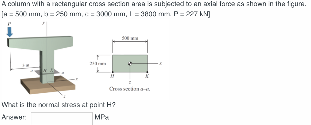 A column with a rectangular cross section area is subjected to an axial force as shown in the figure.
[a =500 mm, b = 250 mm, ¢ = 3000 mm, L = 3800 mm, P = 227 kN]
P y
4 wr
—
3m 250 mm x
a . FE
. H K
Cross section a-a.
What is the normal stress at point H?
Answer: MPa
This is AI generated Response.
Asked by: sneha
Created at: 2025-10-17 12:20:07
Asked by: sneha
Created at: 2025-10-17 12:20:07
Thought Process:
Rendered
Raw Text
**Computing normal stress**
I need to compute the normal stress at point H caused by an eccentric axial load. The problem describes a column with a rectangular cross-sectional area subjected to an axial force, with given dimensions—500 mm by 250 mm and a height of 3000 mm. The force is 227 kN. The figure indicates the column is fixed at the base, and there's an eccentric load. The orientation and dimensions of the cross-section need careful attention, particularly with the axes defined.**Analyzing the cross-section**
I'm inspecting the diagram near cross-section a-a, where it shows the z-axis as vertical. In the figure, the x-axis runs horizontally to the right, while the y-axis represents the vertical axial direction of the column. There’s a bit of confusion here because I see H at the bottom left corner and K near the center of the bottom. The applied load P has an eccentricity relative to the centroid, with a lateral offset of 3 m from it. The dimensions indicate that 'a' is the width at 500 mm and 'b' is the height at 250 mm.**Understanding the loading conditions**
In the diagram, there's a horizontal beam at the top with a load P on its left end, which causes a moment around the column due to an eccentric distance of 3 m. This load is 3 m away from the column's centroid, and the column itself is 3800 mm tall, with the eccentricity of 3000 mm. So, the moment at the base seems to be calculated as P multiplied by c, which affects the bending along the z-axis. The question focuses on finding the normal stress at point H, which is at the bottom left corner of the cross-section, while point K is near the center bottom, creating some confusion.**Determining normal stress at point H**
I'm focusing on finding the normal stress at point H caused by the axial force P, which creates eccentric bending around the z-axis due to the offset c. This isn't about a slender column—it's a basic combination of axial load and bending caused by the eccentricity. The column is vertical along the y-axis, and the line of action is offset along the x-axis. The top beam extends 3 m, and the compressive load P at the beam's left end creates a moment M equal to P times c, bending around the z-axis. In the cross-section, the axes are positioned with z vertical and x horizontal through the centroid.**Assessing stress due to bending and axial load**
I need to determine the normal stress at point H, which is affected by the beam's bending about the z-axis and the axial force P, creating varying stress along the x-coordinate. The bending moment M around the z-axis leads to a stress distribution calculated as σ = -M_z * y / I_z. I’ve concluded that point H, located at coordinates x = -250 mm and z = -125 mm, is influenced by the eccentric loading from the top beam. The moment produced at the column's centroid is M = P * c, affecting the bending stress at this point. The moment is derived from the force's offset and does not rely on the column height.**Evaluating stress components**
I need to determine the stress at point H, factoring in both direct stress and bending moments. The applied axial load P on the beam creates an eccentricity of 3 m along x and possibly along z. I’ve identified that the moment around the z-axis is M_z = P * c with c being 3000 mm, while the vertical dimension and offsets contribute to bending stresses. I’ll calculate the direct stress as σ_0 = P/A and include the effects of bending due to eccentricities measured in both the x and z directions.**Clarifying stress computations**
I’m working through the stress at point H, considering dimensions and eccentricity effects. The vertical dimension of the cross section is likely 250 mm, with a potential horizontal eccentricity of 500 mm. I've noted that the height L = 3800 mm might not be directly used in stress calculations but could be relevant for slenderness. The applied load P of 227 kN translates to a direct stress of 1.816 MPa. For bending stress, I need to calculate the moment of inertia about the z-axis, where the formula is I_z = (b * h^3) / 12 for the rectangular cross section dimensions.**Calculating stress at point H**
I'm calculating the stress at point H considering both direct stress and bending moments. For the moment of inertia, I found I_z to be approximately 2.604e9 mm^4. For bending stress due to M_z, which is positive, I calculated that at point H, the stress is about +65.4 MPa, indicating tension. Additionally, the direct compressive stress was -1.816 MPa. So, the combined net stress at point H comes out to approximately 63.6 MPa tension. I'll need to confirm if there's also bending due to eccentricity affecting this calculation.**Finalizing the stress calculation**
I'm calculating the normal stress at point H, where σ_total(H) combines both direct axial and bending stress components. I find the total stress to be approximately 63.6 MPa in tension. I'll clarify that this is derived from σ0, the compressive stress of -1.816 MPa, and the bending stress of +65.38 MPa.
The approach involves determining the centroid and utilizing superposition: σ = P/A - Mz * x/I_z. I'll summarize the steps clearly, highlight the tension state, and confirm the structural assumptions made during the calculations.
Final Answer:
Rendered
Raw Text
Did you like this answer?
Step 1: Area of the rectangular cross section
A = a·b = 500 mm × 250 mm = 1.25×10^5 mm²
Step 2: Direct (uniform) normal stress from axial force P
σ₀ = P/A = 227 kN / 1.25×10^5 mm²
= 227,000 N / 1.25×10^5 mm² = 1.816 MPa (compression)
Step 3: Bending due to eccentricity of the load
The load acts at an eccentricity c = 3000 mm in the x direction ⇒ a bending moment about the z‑axis:
M_z = P·c = 227,000 N × 3000 mm = 6.81×10^8 N·mm
Second moment of area about the z-axis (vertical centroidal axis):
I_z = (b a³)/12 = 250×500³/12 = 2.604×10^9 mm⁴
Coordinate of point H: x_H = −a/2 = −250 mm
Bending stress at H:
σ_b(H) = −M_z x_H / I_z
= −(6.81×10^8)(−250)/2.604×10^9 = +65.38 MPa (tension)
Step 4: Resultant normal stress at H (superposition)
σ(H) = σ₀ + σ_b(H) = (−1.816) + 65.38 = 63.56 MPa
Answer: 63.6 MPa (tension)
📢 Instructions:
- Ask anything relatd to above question only.
- For new Question goto :