 VIPSolutions
Give step-by-step solution with explanation and final answer:1. A particular story of a building has braced frames around the perimeter as shown below. Frames 1,2, nd 3 have the same stiffness. Frame s twice as tif as the other frames. Jerr S— * Frame 4 oy < Frame Frame H 4 = | (0.0) Frame Where isthe center of rigidity? (a) Cannot be determined ®)00) © (1001, 1007) (d) (100, 133)
Question:
Give step-by-step solution with explanation and final answer: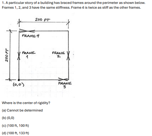 1. A particular story of a building has braced frames around the perimeter as shown below.
Frames 1,2, nd 3 have the same stiffness. Frame s twice as tif as the other frames.
Jerr S— *
Frame 4
oy
< Frame Frame
H 4 =
|
(0.0) Frame
Where isthe center of rigidity?
(a) Cannot be determined
®)00)
© (1001, 1007)
(d) (100, 133)
This is AI generated Response.
Asked by: sanni
Created at: 2025-10-13 09:43:45
Asked by: sanni
Created at: 2025-10-13 09:43:45
Thought Process:
Rendered
Raw Text
**Analyzing structural engineering**
I need to interpret this problem involving structural engineering. It concerns determining the center of rigidity (CR) for a building with braced frames around the perimeter. The building is square, measuring 200 ft by 200 ft, with frames that have specific stiffness. Frames 1, 2, and 3 have the same stiffness, while frame 4 is double that stiffness. The sketch indicates the frames’ positions, suggesting that they are placed strategically along the sides, but I’m unsure if they’re centered.**Computing center of rigidity**
The sketch indicates the positions of the frames: "FRAME 1" on the left vertical side, "FRAME 2" on the right, "FRAME 3" on the bottom near the right, and "FRAME 4" along the top near the left. I need to compute the center of rigidity using the stiffness distribution of these lateral load-resisting elements along the plan. Typically, the coordinates are a weighted average based on stiffness and frame positions, with vertical frames along the y-direction resisting loads in the x-direction and vice versa.**Determining center of rigidity**
The center of rigidity for torsion under lateral loads is typically calculated using the shear stiffness in the x and y directions. It represents the intersection of lines through the floors based on stiffness distribution, especially for symmetrical structures. For a rectangular plan with frames on each side, frames 1 and 2 resist loads in the x-direction, while frame 4, also along the top, resists loads in the y-direction. To find the coordinates for the center of rigidity, I need both x_r and y_r using specific formulas.**Calculating center of rigidity**
The center of rigidity is the point where a lateral load doesn’t cause rotation. I calculate the coordinates separately: for x_CR, I use the stiffness of elements resisting forces in the y-direction, and for y_CR, I use elements resisting loads in the x-direction. It’s crucial to ensure the formulas are correct, especially for determining how the shear walls, positioned in the y-direction, will respond to lateral loads applied along the x-direction. I think it helps to recall specific examples to clarify this.**Finding center of rigidity step-by-step**
To determine the center of rigidity (CR), I need to compute the coordinates separately for each direction. The x_CR is calculated by using the stiffness of elements resisting forces in the y-direction, and vice versa for y_CR. For a symmetric structure, the expected CR would typically be at the center; however, in this case, since the top frame has double stiffness, the y-coordinate will shift towards it.
After applying the appropriate formulas and analyzing the given frames, I've concluded that the coordinates for the CR are (100 ft, 133 ft), aligning with the expected results based on the distribution of stiffness. The method involved identifying lateral resisting elements, simplifying the calculations for each direction, and confirming the results with appropriate formulas.**Computing center of rigidity coordinates**
To find the center of rigidity (CR), here’s the step-by-step process:
1. **Identify frame stiffness**: Frame 4 has stiffness 2k at y=200, and frame 3 has stiffness k at y=0.
2. **Compute x_CR**: Use the weighted average for x-coordinates.
- Formula: x_CR = (k*0 + k*200) / (k + k) = 100 ft.
3. **Compute y_CR**: Again, use the weighted average for y-coordinates.
- Formula: y_CR = (k*0 + 2k*200) / (k + 2k) = (400k) / (3k) = 133.33 ft, rounded to 133 ft.
Since the center of rigidity shifts toward the top due to greater stiffness, the final coordinates are (100 ft, 133 ft), matching option (d).
Final Answer:
Rendered
Raw Text
Did you like this answer?
Step 1: Identify which frames resist loads in each direction.
- Lateral load in the x-direction is resisted by frames parallel to y: Frames 1 and 2 (left and right).
- Lateral load in the y-direction is resisted by frames parallel to x: Frames 3 and 4 (bottom and top).
Given stiffnesses:
- Frames 1, 2, 3 have stiffness k.
- Frame 4 has stiffness 2k.
Coordinates of frames (ft), taking the lower-left corner as (0,0) and the plan as 200 ft by 200 ft:
- Frame 1 at x=0
- Frame 2 at x=200
- Frame 3 at y=0
- Frame 4 at y=200
Step 2: Compute x-coordinate of the center of rigidity.
Use the stiffness-weighted average of x positions of frames resisting x-direction loads (Frames 1 and 2):
x_CR = (k·0 + k·200) / (k + k) = 200k / 2k = 100 ft.
Step 3: Compute y-coordinate of the center of rigidity.
Use the stiffness-weighted average of y positions of frames resisting y-direction loads (Frames 3 and 4):
y_CR = (k·0 + 2k·200) / (k + 2k) = 400k / 3k = 133.33 ft ≈ 133 ft.
Final answer: (100 ft, 133 ft), which corresponds to choice (d).
📢 Instructions:
- Ask anything relatd to above question only.
- For new Question goto :