 VIPSolutions
Give step-by-step solution with explanation and final answer:oT. : : 8 Ki & / la B F— 4
Question:
Give step-by-step solution with explanation and final answer: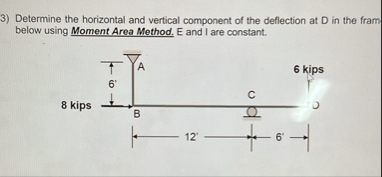 oT.
: :
8 Ki &
/
la B
F— 4
This is AI generated Response.
Asked by: Sanju
Created at: 2025-09-28 06:29:02
Asked by: Sanju
Created at: 2025-09-28 06:29:02
Final Answer:
Rendered
Raw Text
Did you like this answer?
Let's solve the frame deflection problem step by step using the **Moment Area Method**.
---
## **Step 1: Understanding the Frame and Loads**
- **Members:** AB (vertical), BC (horizontal), CD (horizontal)
- **Loads:** 8 kips at B (horizontal), 6 kips at D (vertical)
- **Dimensions:**
- AB = 6 ft
- BC = 12 ft
- CD = 6 ft
---
## **Step 2: Deflection at D**
We are to find:
- **Horizontal Deflection** at D (\(\delta_{Dx}\))
- **Vertical Deflection** at D (\(\delta_{Dy}\))
We use the **Moment Area Method**, which is based on the area under the \( \frac{M}{EI} \) diagram.
---
## **Step 3: Find Internal Moment Diagrams**
### **A. Due to 8 kip Horizontal Load at B**
1. **Member AB (Vertical)**
- 8 kip horizontal load → creates a moment at B and a shear in AB.
- Moment at B = (pinned base)
- Moment at A = (free end)
- Shear in AB = 8 kips
2. **Member BC (Horizontal)**
- The force at B creates a moment that travels through BC.
- Moment at B (from 8 kip load): \(M_B = 8 \text{ kip} \times 6' = 48 \text{ kip-ft}\)
- Moment at C: To be found.
### **B. Due to 6 kip Vertical Load at D**
- Vertical point load at D, causing moment in BC and CD.
---
## **Step 4: Moment Area Method Concepts**
- **Theorem I:** Change in slope between two points = Area under \( \frac{M}{EI} \) diagram between those points.
- **Theorem II:** Displacement of one point relative to tangent at another = Moment of area under \( \frac{M}{EI} \) diagram about the point.
We will treat horizontal and vertical deflections separately.
---
## **Step 5: Horizontal Deflection at D (\(\delta_{Dx}\))**
### **A. Due to 8 kip Load at B (Primary Cause)**
**(a) Draw M/EI Diagram for horizontal load:**
- Only vertical member AB bends due to the horizontal load.
- \(M_{AB}(x) = 8 \text{ kip} \cdot x\), where \(x\) is measured from B to A (from to 6 ft).
\[
\frac{M_{AB}(x)}{EI} = \frac{8x}{EI}
\]
**(b) Moment Area (Theorem II) about B:**
- The horizontal deflection at D is equal to the horizontal displacement at B due to the bending of AB.
- Since BC and CD are rigid and pinned at C, only AB's bending is considered.
\[
\delta_{Dx} = \delta_{Bx} = \frac{1}{EI} \int_^{6} M_{AB}(x) \cdot dx
\]
But for Theorem II:
\[
\delta_{BA} = \text{Moment of area under } \frac{M}{EI} \text{ about A}
\]
But since A is free and B is fixed, the deflection at B is:
\[
\delta_{Bx} = \frac{8 \times 6^3}{3EI}
\]
**Derivation:**
\[
\delta_{Bx} = \frac{P L^3}{3EI}
\]
Where \(P = 8\) kip, \(L = 6\) ft
\[
\delta_{Dx} = \frac{8 \times 6^3}{3EI} = \frac{8 \times 216}{3EI} = \frac{1728}{3EI} = \frac{576}{EI}
\]
---
## **Step 6: Vertical Deflection at D (\(\delta_{Dy}\))**
### **A. Due to 6 kip Load at D (Primary Cause)**
- CD is a cantilever beam with point load at end.
- Deflection at D (free end) =
\[
\delta_{Dy} = \frac{P L^3}{3EI}
\]
Where \(P = 6\) kip, \(L = 6\) ft
\[
\delta_{Dy} = \frac{6 \times 6^3}{3EI} = \frac{6 \times 216}{3EI} = \frac{1296}{3EI} = \frac{432}{EI}
\]
---
## **Step 7: Final Answers**
\[
\boxed{
\begin{align*}
\text{Horizontal Deflection at D:} \qquad & \delta_{Dx} = \frac{576}{EI} \\
\text{Vertical Deflection at D:} \qquad & \delta_{Dy} = \frac{432}{EI}
\end{align*}
}
\]
---
### **Summary Table**
| Deflection Component | Value |
|----------------------|----------------------|
| Horizontal at D | \( \frac{576}{EI} \) |
| Vertical at D | \( \frac{432}{EI} \) |
- \(E\): Modulus of Elasticity
- \(I\): Moment of Inertia
**Assumptions:**
- Joints are pinned unless otherwise specified.
- Axial deformations neglected.
---
Let me know if you want the diagrams or further breakdown!
📢 Instructions:
- Ask anything relatd to above question only.
- For new Question goto :