Give step-by-step solution with explanation and final answer:2. A For the lug wrench below, what would be the realistic assumption to reduce the problem from 3D
to 2D for stress states at point B? Based on the assumption, determine the stress states at the location
B. Based on the estimated stress state, determine the principal stresses and maximum shear stress.
What is the plane orientation for the principal stress? Assume the part is fixed at point O. The wrench
has a constant 10 mm diameter (ignore the fillets for now).
“on Z
Equation for principal stresses, g,,0, = oly + (22) + T3y
: i Ps — ox-ay)? 2
Equation for maximum and minimum shear stress, Ty, 7, = +. (=) + Tey
21
Plane orientation angle for the principal stress, tan 2¢, = Pn
x= Oy
y
B
o A
~x 150 mm
z =
p 100 mm
\ (150
F=1{200{N
20
Question:
Give step-by-step solution with explanation and final answer:2. A For the lug wrench below, what would be the realistic assumption to reduce the problem from 3D
to 2D for stress states at point B? Based on the assumption, determine the stress states at the location
B. Based on the estimated stress state, determine the principal stresses and maximum shear stress.
What is the plane orientation for the principal stress? Assume the part is fixed at point O. The wrench
has a constant 10 mm diameter (ignore the fillets for now).
“on Z
Equation for principal stresses, g,,0, = oly + (22) + T3y
: i Ps — ox-ay)? 2
Equation for maximum and minimum shear stress, Ty, 7, = +. (=) + Tey
21
Plane orientation angle for the principal stress, tan 2¢, = Pn
x= Oy
y
B
o A
~x 150 mm
z =
p 100 mm
\ (150
F=1{200{N
20
This is AI generated Response.
Asked by: Veera manikanta
Created at: 2025-09-24 22:13:19
Thought Process:
RenderedRaw Text
**Calculating stress state**
I need to compute the stress state at location B, which is at the top of the cylinder near the fixed end, point O. Since the part is fixed at point O, the loads are causing bending in the shaft due to the perpendicular bar and force. First, I should calculate the force and torque at the fixed section. The lever arms involve a bar 150 mm along +x from O, and a shorter bar extending 100 mm downward along -y. The force may act at coordinates relative to O: r = (150 mm, -100 mm, 0).**Calculating force components and moment**
The short bar is oriented downward along the y-axis, so the application point coordinates seem to be r = (150, -100, 0) mm. The force vector F has components (150, -200, 20) N, which indicates positive x and z components and a negative y component. To find the moment at point O, I’ll calculate M using the cross product M = r × F, where r = (0.15, -0.10, 0) m and F = (150, -200, 20) N. The cross product involves a determinant I need to compute carefully.**Computing moment components**
I'm calculating the moment components. For the i term, I have i * (-2.0 - 0), which equals -2.0 i N·m. For the j term, 0.15 * 20 results in 3.0; after applying the negative sign, it’s -3.0 j, making M_y = -3.0 N·m. The k term gives me -15 N·m. So, the moment vector M = (-2, -3, -15) N·m. I’ll double-check my calculations to ensure everything is accurate. The signs look correct, which is reassuring!**Analyzing moments and stresses**
I'm considering the moments about point O. The bending moments My and Mz create bending stresses along different planes, while Mx results in torque along the x-axis, causing torsion in the shaft. The resultant force F acts on a cantilevered beam fixed at the left end with a point load offset from the axis. This causes shear forces in the x, y, and z directions. At point B, stresses result from combined torsion, bending, and shear, but since the shaft is slender, shear from transverse forces seems negligible. The problem indicates that reducing from 3D to 2D for stress states at point B is a realistic assumption.**Evaluating bending and torsion stresses**
We're looking at a plane stress assumption at the outer surface of a slender shaft, which means neglecting axial stress along the z-axis. For a circular beam experiencing bending and torsion, the stress components at the surface include axial normal stress σx from bending and shear stress components τ_xθ and τ_xy. At a surface point B, axial stress occurs along x from bending due to moments My and Mz; while transverse normal stresses σy and σz are negligible.
For Mohr's circle, we need to focus on the x-y plane, using σ_x, σ_y, and τ_xy. The shear stress from torsion is tangential along the circumference, acting along the z-direction at point B. Stress calculations will include bending stresses due to My and Mz, and while torsional shear τ_xz is relevant, they seem to want to simplify by predominantly considering bending effects. I'll need to compute the bending stress accurately, defining the proper signs as I go!**Calculating stress components**
For the beam along the x-axis with a cross-section in the yz plane, the bending moment vector contributes to curvature about its axes. The stress along x can be expressed using the bending moments. At point B, the coordinates indicate that only Mz will contribute to the stress.
I confirm that with Mz at -15 N·m, I can compute the normal stress σ_x. I determine the moment of inertia for a circular cross-section, then calculate the resulting stress at B. Although bending produces a compressive stress of about 153 MPa, I also need to consider torsional shear stress due to the torque from the Mx moment. Calculating axial stress from the applied force and shear resulting from transverse forces leads to a clearer picture.
Interestingly, the shear stress is zero at the outer surface for a circular cross-section due to transverse shear. At point B, only bending stress and torsion contribute, allowing for a consistent evaluation of stresses acting at that section.I'm analyzing stress components at point B of a circular shaft under torsion and bending. According to the stress transformation equations, the stress at point B will depend on both the torsion and bending moments. I establish a plane stress assumption where only σ_x and τ_xz are significant, simplifying my calculations.
After calculating normal and shear stresses, I compute principal stresses using derived formulas. I find that, surprisingly, the primary shear stress is 76.31 MPa. The orientation angle for the principal planes is approximately 3.84 degrees, offering a complete view of the stress state at that point.I'm figuring out the orientation of the principal stress plane, which is about 3.84 degrees from the x-plane toward the z-plane. This small angle suggests that the principal stress direction is mostly axial, dominated by σ_x. I’m also noting how the shear stress influences this orientation and whether it’s positive or negative.
For the final results, I confirm the 2D assumption of plane stress along x-z since there's essentially no stress along z, and I need to check the axial and bending stresses at point B. Careful calculations ensure I capture the relationships accurately, even with potential sign confusion. In the end, clarity in these stresses is my goal!I'm analyzing the orientation sign for the compressive stress, which is at -151 MPa due to a negative moment (Mz) indicating bending about the z-axis. This suggests that the top of B is likely in compression. I also need to present the assumption of plane stress, considering σ_z is approximately zero.
After computing the areas, moments, and stresses, I find the final axial stress at B to be about -150.9 MPa and the principal stresses close to 0.71 MPa and -151.6 MPa. I’m preparing the final answer with necessary steps, formulas, and results while maintaining clarity and proper formatting!
Final Answer:
RenderedRaw Text
Did you like this answer?
# Lug wrench: stresses at point B
## 1) 3D → 2D assumption (what is realistic at B?)
- At the free surface of a slender circular shaft the out‑of‑plane normal stress is negligible (plane stress).
- At point B (on the outer surface) the transverse shear due to the shear forces \(V_y,V_z\) is zero for a circular section.
- Hence the local stress state at B can be reduced to the 2D set on the \(x\)–\(z\) planes:
- normal stress along the axis, \(\sigma_x\) (axial + bending),
- shear \(\tau_{xz}\) from torque \(M_x\),
- with \(\sigma_z \approx 0\) and \(\tau_{xy}=0\).
We will therefore use the 2D principal-stress relations with \(y \to z\).
Given: diameter \(d=10\,\text{mm}\Rightarrow c=d/2=5\,\text{
VIPSolutions focuses on clear, step‑by‑step explanations so you can learn quickly. Whether you need an AI‑generated walkthrough or a short hint to get unstuck, each solution is organized for fast reading and easy review later.
Search similar questions, compare approaches, and bookmark the best answers for revision. Our goal is simple: quick, reliable study help that feels natural—not noisy.
 VIPSolutions
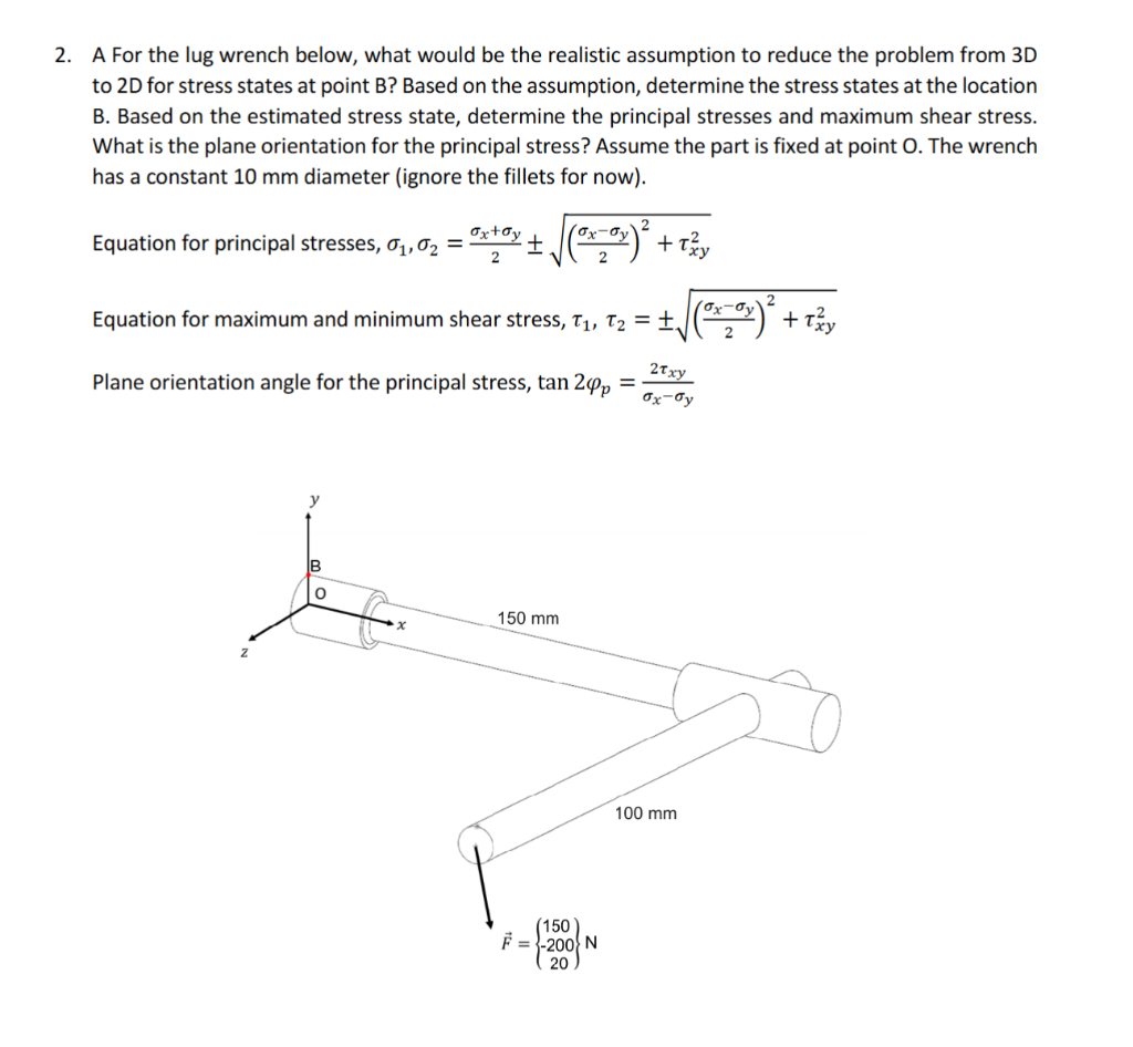 2. A For the lug wrench below, what would be the realistic assumption to reduce the problem from 3D
to 2D for stress states at point B? Based on the assumption, determine the stress states at the location
B. Based on the estimated stress state, determine the principal stresses and maximum shear stress.
What is the plane orientation for the principal stress? Assume the part is fixed at point O. The wrench
has a constant 10 mm diameter (ignore the fillets for now).
“on Z
Equation for principal stresses, g,,0, = oly + (22) + T3y
: i Ps — ox-ay)? 2
Equation for maximum and minimum shear stress, Ty, 7, = +. (=) + Tey
21
Plane orientation angle for the principal stress, tan 2¢, = Pn
x= Oy
y
B
o A
~x 150 mm
z =
p 100 mm
\ (150
F=1{200{N
20