 VIPSolutions
Give step-by-step solution with explanation and final answer:Referring to Figure QS, the connected loads have the following ratings: 120 V secondar 2400 V primary a - 2 on | [TT > o 208V alin NEED BED 2 ° 120V EEE Tinl TI — ground single phase loads Mi(e) ()M2 phase loads Figure Q5 Three-phase, 4-wire, 208 V/120 V distribution system. Single phase loads: 25 kW each Motor M1: 50 kVA, cos 6 = 0.60 lagging Motor M2: 160 kVA, cos 6 = 0.70 lagging a. Calculate the currents in the secondary windings. b. Calculate the line currents and power factor on the 2400 V side.
Question:
Give step-by-step solution with explanation and final answer: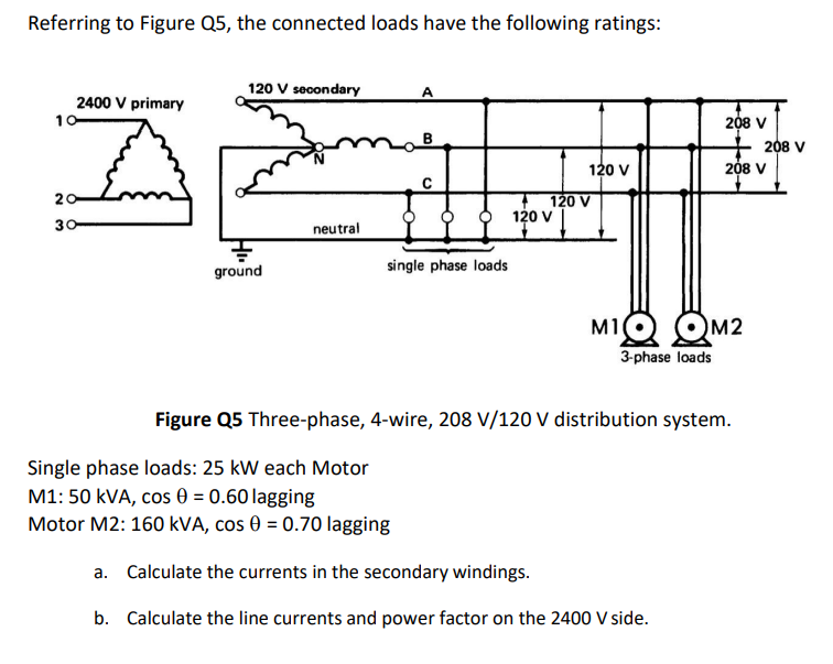 Referring to Figure QS, the connected loads have the following ratings:
120 V secondar
2400 V primary a - 2
on | [TT
> o 208V
alin NEED BED
2 ° 120V
EEE Tinl
TI —
ground single phase loads
Mi(e) ()M2
phase loads
Figure Q5 Three-phase, 4-wire, 208 V/120 V distribution system.
Single phase loads: 25 kW each Motor
M1: 50 kVA, cos 6 = 0.60 lagging
Motor M2: 160 kVA, cos 6 = 0.70 lagging
a. Calculate the currents in the secondary windings.
b. Calculate the line currents and power factor on the 2400 V side.
This is AI generated Response.
Asked by: A j mahant
Created at: 2025-09-13 08:48:44
Asked by: A j mahant
Created at: 2025-09-13 08:48:44
Final Answer:
Rendered
Raw Text
Did you like this answer?
Let's solve the problem step by step.
---
## **Given Data**
- **Single Phase Loads:** 25 kW each (assume three, one per phase)
- **Motor M1:** 50 kVA, cos θ = 0.60 lagging (3-phase, 208 V)
- **Motor M2:** 160 kVA, cos θ = 0.70 lagging (3-phase, 208 V)
- **Secondary Voltages:** 208 V (line-to-line), 120 V (line-to-neutral)
- **Primary Voltage:** 2400 V (delta)
- **Transformer:** Y-connected secondary
---
## **Step 1: Calculate Currents in the Secondary Windings**
### **A. Single-Phase Loads**
Each single-phase load = 25 kW at 120 V (assume unity power factor unless stated):
\[
I_{single-phase} = \frac{P}{V} = \frac{25000}{120} = 208.33~\text{A} \quad \text{(per phase)}
\]
---
### **B. Motor Loads (3-phase)**
#### **Motor M1**
- \( S_1 = 50\,\text{kVA} \)
- \( V_{LL} = 208\,\text{V} \)
- \(\cos \theta = 0.60 \)
\[
I_{M1} = \frac{S_1}{\sqrt{3} V_{LL}} = \frac{50000}{\sqrt{3} \times 208} = \frac{50000}{360.8} = 138.5~\text{A}
\]
#### **Motor M2**
- \( S_2 = 160\,\text{kVA} \)
- \( V_{LL} = 208\,\text{V} \)
- \(\cos \theta = 0.70 \)
\[
I_{M2} = \frac{S_2}{\sqrt{3} V_{LL}} = \frac{160000}{\sqrt{3} \times 208} = \frac{160000}{360.8} = 443.5~\text{A}
\]
---
### **C. Total Currents in Each Secondary Winding**
Each phase winding carries:
- The single-phase load (one per phase)
- 3-phase load current (divide equally among phases)
\[
I_{sec,\,phase} = I_{single-phase} + \left(I_{M1} + I_{M2}\right)
\]
But for 3-phase loads: The phase current is equal to line current (for Y connection):
\[
I_{phase,\,3\text{-}\phi} = I_{line,\,3\text{-}\phi}
\]
So, **per phase total:**
\[
I_{total,\,phase} = I_{single-phase} + I_{M1} + I_{M2}
\]
\[
I_{total,\,phase} = 208.3 + 138.5 + 443.5 = \boxed{790.3~\text{A}}
\]
---
## **Step 2: Line Currents and Power Factor on the 2400 V Side**
### **A. Total Apparent Power on Secondary Side**
- Single-phase loads: 3 × 25 kW = 75 kW (assume unity PF, so 75 kVA)
- Motor M1: 50 kVA, PF = 0.60
- Motor M2: 160 kVA, PF = 0.70
\[
S_{total} = S_{single-phase} + S_{M1} + S_{M2} = 75 + 50 + 160 = 285\,\text{kVA}
\]
#### **Total Real Power \(P_{total}\):**
\[
P_{M1} = 50 \times 0.60 = 30\,\text{kW}
\]
\[
P_{M2} = 160 \times 0.70 = 112\,\text{kW}
\]
\[
P_{total} = 75 + 30 + 112 = 217\,\text{kW}
\]
#### **Total Reactive Power \(Q_{total}\):**
\[
Q_{M1} = 50 \times \sin(\cos^{-1}(0.60)) = 50 \times 0.8 = 40\,\text{kVAR}
\]
\[
Q_{M2} = 160 \times \sin(\cos^{-1}(0.70)) = 160 \times 0.7141 = 114.25\,\text{kVAR}
\]
\[
Q_{total} = 0 + 40 + 114.25 = 154.25\,\text{kVAR}
\]
---
### **B. Total Apparent Power**
\[
S_{total} = \sqrt{P_{total}^2 + Q_{total}^2}
\]
\[
S_{total} = \sqrt{217^2 + 154.25^2} = \sqrt{47089 + 23793} = \sqrt{70882} = 266.5\,\text{kVA}
\]
---
### **C. Total Line Current on Primary Side (2400 V)**
\[
I_{primary} = \frac{S_{total}}{\sqrt{3} \times V_{primary}}
\]
\[
I_{primary} = \frac{266500}{\sqrt{3} \times 2400} = \frac{266500}{4156.9} = 64.1\,\text{A}
\]
---
### **D. Power Factor on Primary Side**
\[
\text{PF}_{primary} = \frac{P_{total}}{S_{total}} = \frac{217}{266.5} = 0.814
\]
---
## **Final Answers**
### **a. Currents in the secondary windings**
- **Per phase (secondary winding):**
\(\boxed{790.3~\text{A}}\)
### **b. Line currents and power factor on the 2400 V side**
- **Line current:**
\(\boxed{64.1~\text{A}}\)
- **Power factor:**
\(\boxed{0.814~\text{lagging}}\)
---
**Let me know if you need phasor diagrams or further breakdowns!**
📢 Instructions:
- Ask anything relatd to above question only.
- For new Question goto :