 VIPSolutions
Give step-by-step solution with explanation and final answer:3) Consider the switching diode circuits of Fig. P3.3 for > 0 when the switch is turned on. (a) Derive expressions for ip(t). isw(f). and ve(r). Assume ip (0) = 1.07, and v¢(0) = V,.. Suggest possible switch implementations (unidirectional or bidirectional). Fig. P3.3 yw L iO) =1, 3 ve(0)=V, Ig ® A t=0 Ve c Ap
Question:
Give step-by-step solution with explanation and final answer: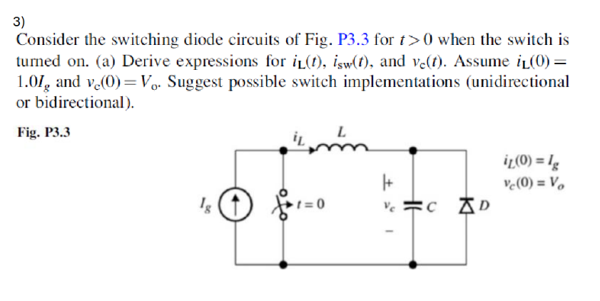 3)
Consider the switching diode circuits of Fig. P3.3 for > 0 when the switch is
turned on. (a) Derive expressions for ip(t). isw(f). and ve(r). Assume ip (0) =
1.07, and v¢(0) = V,.. Suggest possible switch implementations (unidirectional
or bidirectional).
Fig. P3.3 yw L
iO) =1,
3 ve(0)=V,
Ig ® A t=0 Ve c Ap
This is AI generated Response.
Asked by: mayank
Created at: 2025-09-10 08:35:00
Asked by: mayank
Created at: 2025-09-10 08:35:00
Final Answer:
Rendered
Raw Text
Did you like this answer?
Let's solve the problem step-by-step:
---
# **Step 1: Understanding the Circuit**
- At \( t = 0 \), the switch closes.
- The initial conditions are:
- \( i_L(0) = I_g \)
- \( v_C(0) = V_o \)
- We are to find expressions for:
- \( i_L(t) \): Inductor current
- \( i_{sw}(t) \): Switch current
- \( v_C(t) \): Capacitor voltage
---
# **Step 2: Drawing the Equivalent Circuit**
**For \( t > 0 \) (Switch Closed):**
- The source \( I_g \) is applied to the LC circuit via the switch.
- The diode orientation allows current from left to right (as shown).
- The circuit forms a series LC loop with a parallel diode and current source.
---
# **Step 3: Writing the Differential Equations**
**KCL at the top node:**
\[
I_g = i_{sw}(t) + i_L(t)
\]
**KVL around the LC loop:**
\[
v_L + v_C = 0
\]
- \( v_L = L \frac{di_L}{dt} \)
- \( v_C = \frac{1}{C} \int i_C dt \)
But, \( i_C = C \frac{dv_C}{dt} \) and \( i_L = i_C \) (since they are in series in the right loop).
So,
\[
L \frac{di_L}{dt} + v_C = 0
\]
\[
i_L = C \frac{dv_C}{dt}
\]
or,
\[
\frac{di_L}{dt} = -\frac{1}{L} v_C
\]
\[
i_L = C \frac{dv_C}{dt}
\]
---
# **Step 4: Second-order Differential Equation**
Substitute \( i_L \) into the first equation:
\[
L \frac{d}{dt}(C \frac{dv_C}{dt}) + v_C = 0
\]
\[
LC \frac{d^2 v_C}{dt^2} + v_C = 0
\]
\[
\frac{d^2 v_C}{dt^2} + \frac{1}{LC} v_C = 0
\]
This is a standard second-order homogeneous differential equation with solution:
\[
v_C(t) = A \cos(\omega_0 t) + B \sin(\omega_0 t)
\]
Where \( \omega_0 = \frac{1}{\sqrt{LC}} \).
---
# **Step 5: Applying Initial Conditions**
- \( v_C(0) = V_o \)
- \( i_L(0) = C \frac{dv_C}{dt}\bigg|_{t=0} = I_g \)
Find \( \frac{dv_C}{dt}\bigg|_{t=0} \):
\[
\frac{dv_C}{dt} = -A\omega_0 \sin(\omega_0 t) + B\omega_0 \cos(\omega_0 t)
\]
At \( t=0 \):
\[
\frac{dv_C}{dt}\bigg|_{t=0} = B\omega_0
\]
So,
\[
I_g = C \cdot B \omega_0 \implies B = \frac{I_g}{C \omega_0}
\]
From \( v_C(0) = V_o \implies A = V_o \).
---
# **Step 6: Final Expressions**
### **Capacitor Voltage**
\[
\boxed{v_C(t) = V_o \cos(\omega_0 t) + \frac{I_g}{C\omega_0} \sin(\omega_0 t)}
\]
### **Inductor Current**
\[
i_L(t) = C \frac{dv_C}{dt}
\]
\[
\frac{dv_C}{dt} = -V_o \omega_0 \sin(\omega_0 t) + \frac{I_g}{C} \cos(\omega_0 t)
\]
\[
i_L(t) = -V_o C \omega_0 \sin(\omega_0 t) + I_g \cos(\omega_0 t)
\]
So,
\[
\boxed{i_L(t) = I_g \cos(\omega_0 t) - V_o C \omega_0 \sin(\omega_0 t)}
\]
### **Switch Current**
\[
i_{sw}(t) = I_g - i_L(t)
\]
\[
= I_g - \left[ I_g \cos(\omega_0 t) - V_o C \omega_0 \sin(\omega_0 t) \right]
\]
\[
= I_g [1 - \cos(\omega_0 t)] + V_o C \omega_0 \sin(\omega_0 t)
\]
So,
\[
\boxed{i_{sw}(t) = I_g [1 - \cos(\omega_0 t)] + V_o C \omega_0 \sin(\omega_0 t)}
\]
---
# **Step 7: Switch Implementation**
- **Unidirectional Switch:** Since the current source \( I_g \) only delivers current in one direction and the diode allows current only one way, a unidirectional switch (like a MOSFET or IGBT) is sufficient.
- **Bidirectional Switch:** Not required in this configuration.
---
## **Summary Table**
| Quantity | Expression |
|-----------------|--------------------------------------------------------------------------------------|
| \( v_C(t) \) | \( V_o \cos(\omega_0 t) + \frac{I_g}{C\omega_0} \sin(\omega_0 t) \) |
| \( i_L(t) \) | \( I_g \cos(\omega_0 t) - V_o C \omega_0 \sin(\omega_0 t) \) |
| \( i_{sw}(t) \) | \( I_g [1 - \cos(\omega_0 t)] + V_o C \omega_0 \sin(\omega_0 t) \) |
| \( \omega_0 \) | \( \frac{1}{\sqrt{LC}} \) |
**Switch Type:** Unidirectional (e.g., standard MOSFET or IGBT).
---
Let me know if you want a plot or further explanation of the time-domain behavior!
📢 Instructions:
- Ask anything relatd to above question only.
- For new Question goto :