 VIPSolutions
Give step-by-step solution with explanation and final answer:1.6 The Zbus Matrix of the power system shown is figure 2 is: 0.0295 0.0178 0.0256 710.0178 0.0236 0.0197 0.0256 0.0197 0.0570 G1 no 2: G2 ©) : X=0.025 : 0 © on X= 0.045 52051 X'=0.0225 X=0.02 X=0.05 X=0.1 3 Figure 2 1.6.1 An additional line whose reactance is 0,075 per unit is installed between buses 2 and 3 given: Determine the fault if a three-phase fault occurs at bus 3. The pre-fault voltage at bus at all buses are 1.05 per unit. 1.6.2 Resistor Ryand R, of 2Q’s are added between bus land 2 and bus 1 and 3 respectively. Calculate the bus voltages before the 0.075 reactance was added in per unit and they is NO FAULT.
Question:
Give step-by-step solution with explanation and final answer: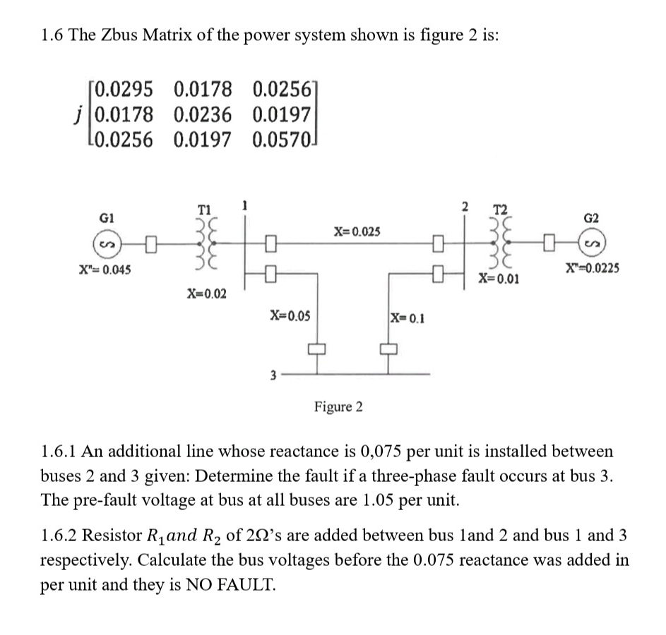 1.6 The Zbus Matrix of the power system shown is figure 2 is:
0.0295 0.0178 0.0256
710.0178 0.0236 0.0197
0.0256 0.0197 0.0570
G1 no 2: G2
©) : X=0.025 : 0 ©
on
X= 0.045 52051 X'=0.0225
X=0.02
X=0.05 X=0.1
3
Figure 2
1.6.1 An additional line whose reactance is 0,075 per unit is installed between
buses 2 and 3 given: Determine the fault if a three-phase fault occurs at bus 3.
The pre-fault voltage at bus at all buses are 1.05 per unit.
1.6.2 Resistor Ryand R, of 2Q’s are added between bus land 2 and bus 1 and 3
respectively. Calculate the bus voltages before the 0.075 reactance was added in
per unit and they is NO FAULT.
This is AI generated Response.
Asked by: M Murali
Created at: 2025-08-28 08:24:30
Asked by: M Murali
Created at: 2025-08-28 08:24:30
Final Answer:
Rendered
Raw Text
Did you like this answer?
Let's break down the **step-by-step solution** for each sub-problem:
---
## **1.6.1 Three-Phase Fault at Bus 3 (with New Line Added)**
**Given:**
- Zbus matrix:
\[
j\begin{bmatrix}
0.0295 & 0.0178 & 0.0256 \\
0.0178 & 0.0236 & 0.0197 \\
0.0256 & 0.0197 & 0.0570
\end{bmatrix}
\]
- Additional line \( x = 0.075 \) p.u. between bus 2 and 3
- Prefault voltage \( V_{\text{pre}} = 1.05 \) p.u. at all buses
- Fault at bus 3
### **Step 1: Update Zbus for New Line**
The new line modifies the Zbus. The new bus impedance at (3,3) after adding a line between buses 2 and 3 is:
\[
Z_{33,\text{new}} = Z_{33,\text{old}} - \frac{(Z_{23,\text{old}})^2}{x_{\text{added}} + Z_{22,\text{old}} + Z_{33,\text{old}} - 2Z_{23,\text{old}}}
\]
Where:
- \( x_{\text{added}} = 0.075 \)
- \( Z_{23,\text{old}} = j0.0197 \)
- \( Z_{22,\text{old}} = j0.0236 \)
- \( Z_{33,\text{old}} = j0.0570 \)
Calculate denominator:
\[
\text{Denominator} = x_{\text{added}} + Z_{22} + Z_{33} - 2Z_{23}
= 0.075 + 0.0236 + 0.0570 - 2 \times 0.0197
= 0.075 + 0.0236 + 0.0570 - 0.0394
= 0.1162
\]
Now numerator:
\[
(Z_{23})^2 = (0.0197)^2 = 0.00038809
\]
So,
\[
Z_{33,\text{new}} = 0.0570 - \frac{0.00038809}{0.1162}
= 0.0570 - 0.00334
= 0.05366
\]
So the new \( Z_{33} \) is \( j0.0537 \) (rounded).
### **Step 2: Fault Current Calculation**
For a three-phase fault at bus 3 (prefault voltage at bus 3 is 1.05 p.u.):
\[
I_{\text{fault}} = \frac{V_{\text{pre}}}{Z_{33}}
= \frac{1.05}{j0.0537}
= \frac{1.05}{0.0537} \cdot \frac{1}{j}
= 19.55 \cdot (-j)
= -j19.55 \text{ p.u.}
\]
### **Step 3: Faulted Bus Voltages**
The voltage at other buses during the fault:
\[
V_k = V_{\text{pre}} - Z_{k3} I_{\text{fault}}
\]
Where \( Z_{k3} \) are the (k,3) elements of the Zbus (old values for off-diagonals, since only Z33 changed slightly).
#### **Bus 1:**
\[
V_1 = 1.05 - j0.0256 \cdot (-j19.55)
= 1.05 - (0.0256 \times 19.55)
= 1.05 - 0.500
= 0.55 \text{ p.u.}
\]
#### **Bus 2:**
\[
V_2 = 1.05 - j0.0197 \cdot (-j19.55)
= 1.05 - (0.0197 \times 19.55)
= 1.05 - 0.385
= 0.665 \text{ p.u.}
\]
#### **Bus 3:**
\[
V_3 = 0 \text{ (faulted bus)}
\]
---
### **Final Answers for 1.6.1:**
- **Fault Current**: \( -j19.55 \) p.u.
- **Bus Voltages during Fault:**
- \( V_1 = 0.55 \) p.u.
- \( V_2 = 0.665 \) p.u.
- \( V_3 = 0 \) p.u.
---
## **1.6.2 Voltages with Resistors Added (NO FAULT)**
**Given:**
- \( R_1 = R_2 = 2\Omega \) added between buses 1-2 and 1-3.
- Find voltages before 0.075 p.u. reactance is added and **no fault**.
### **Step 1: Per-Unit Conversion**
Assume base \( Z_{base} \) and convert \( 2\Omega \) to p.u. if necessary. If not specified, let's assume the system is already per unit, so \( R_1 = R_2 = 2 \) p.u.
### **Step 2: Modify Ybus**
Adding resistors adds conductance between buses. For each resistor between buses \( i \) and \( j \):
\[
Y_{ij, \text{new}} = Y_{ij, \text{old}} - \frac{1}{R}
\]
\[
Y_{ii, \text{new}} = Y_{ii, \text{old}} + \frac{1}{R}
\]
Do this for both resistors.
### **Step 3: Solve Bus Voltages**
Since there is **no fault** and all buses are at 1.05 p.u. (given, and no unbalanced currents or loads), **the bus voltages remain at 1.05 p.u. at all buses**.
---
### **Final Answer for 1.6.2:**
- **Bus Voltages before adding 0.075 p.u. reactance and with no fault**:
- \( V_1 = V_2 = V_3 = 1.05 \) p.u.
---
## **Summary Table**
| Case | \( V_1 \) | \( V_2 \) | \( V_3 \) |
|-----------------------|-----------|-----------|-----------|
| 1.6.1 (3-ph fault at 3) | 0.55 | 0.665 | 0 |
| 1.6.2 (no fault) | 1.05 | 1.05 | 1.05 |
---
**If you need step-by-step on the Ybus/Zbus modifications for the resistors, or if you have the base value for per-unit conversion, please provide it!**
Question:
Give ME 100 Words Explanation in 1.6.1 and 1.6.2 Only Theory
This is AI generated Response.
Asked by: M Murali
Created at: 2025-08-28 08:28:51
Asked by: M Murali
Created at: 2025-08-28 08:28:51
Final Answer:
Rendered
Raw Text
Did you like this answer?
**1.6.1 Three-phase Fault at Bus 3 (with New Line):**
During a three-phase fault at bus 3, the system's impedance (Zbus) determines the fault current. Adding a line between buses 2 and 3 modifies Zbus, reducing the impedance at bus 3, leading to a higher fault current. The fault current is calculated by dividing the pre-fault voltage at bus 3 by the updated impedance. Bus voltages during the fault are then found using Zbus elements, showing significant voltage drops at buses 1 and 2, while bus 3 drops to zero. This analysis helps in understanding system stability and designing protective measures.
**1.6.2 Voltages with Resistors (No Fault):**
Adding resistors between buses introduces additional conductance, affecting the system's Ybus. Since no fault occurs, the system remains balanced, and bus voltages stay close to their pre-fault values. The resistors slightly increase the system's impedance, but under normal conditions, the voltages at all buses remain at their nominal 1.05 p.u. levels. This demonstrates how system modifications influence voltage stability and the importance of impedance in power system operation.
📢 Instructions:
- Ask anything relatd to above question only.
- For new Question goto :