Give step-by-step solution with explanation and final answer:3- Switches | and 2 in the circuit shown are synchronized. When switch 11is opened, switch
2 closes and vice versa. Switch 1 has been open a long time before closing at 1-0. Find
ile) for 10.
oo | Swicki 0
SF ER
Question:
Give step-by-step solution with explanation and final answer:3- Switches | and 2 in the circuit shown are synchronized. When switch 11is opened, switch
2 closes and vice versa. Switch 1 has been open a long time before closing at 1-0. Find
ile) for 10.
oo | Swicki 0
SF ER
This is AI generated Response.
Asked by: ravi
Created at: 2025-08-13 17:22:34
Final Answer:
RenderedRaw Text
Did you like this answer?
Let's break down the problem step by step:
### **Step 1: Understanding the Problem**
- **Switches 1 and 2 are synchronized.** When one closes, the other opens.
- **Switch 1 has been open for a long time** before closing at \( t = 0 \).
- **At \( t = 0 \):** Switch 1 closes, Switch 2 opens.
- **We are to find \( i_L(t) \), the current through the inductor (316 mH), for \( t \geq 0 \).**
---
### **Step 2: Analyze the Circuit for \( t < 0 \) ("Steady State" Just Before Switching)**
**Switch 1 is OPEN, Switch 2 is CLOSED:**
- The left circuit (with voltage source, resistor, and capacitor) is isolated from the right circuit (with current source, inductor, and resistor).
- The **inductor will act as a short circuit** in steady-state DC (for a long time), so all current from the 10 A source will flow through the 1 kΩ resistor and the inductor.
#### **Find initial inductor current (\( i_L(0^-) \)):**
- **Inductor in steady-state:** Short circuit.
- **Current through inductor:** All of the 10 A from the current source passes through the inductor.
- **So:** \[
i_L(0^-) = 10~A
\]
---
### **Step 3: Analyze the Circuit for \( t \geq 0 \) (After Switching)**
**Switch 1 is CLOSED, Switch 2 is OPEN:**
- Now, the left branch (80 V, 10 Ω, 250 μF) is connected to the right branch (316 mH, 1 kΩ), but the current source is disconnected (Switch 2 open).
- The circuit is now a **series RLC circuit**:
\[
80~V \rightarrow 10~\Omega \rightarrow 250~\mu F \rightarrow 316~mH \rightarrow 1~k\Omega
\]
But we are interested in the current through the **inductor** after switching, \( i_L(t) \).
---
### **Step 4: Write the Loop Equation for \( t \geq 0 \)**
Let’s define current \( i(t) \) as the current through the inductor and the series circuit after \( t=0 \):
\[
80 - 10i - v_C - 1000i - 316 \cdot 10^{-3}\frac{di}{dt} = 0
\]
Where \( v_C \) is the voltage across the capacitor.
But, for a **series RLC circuit**, the KVL loop is:
\[
V_{source} = V_R + V_L + V_C
\]
\[
80 = (10 + 1000)i + 316 \cdot 10^{-3}\frac{di}{dt} + v_C
\]
But we need everything in terms of \( i \):
\[
v_C = \frac{1}{C} \int i(t)dt
\]
But a more straightforward approach is to write the **differential equation** for an RLC series circuit:
\[
V_{source} = Ri + L\frac{di}{dt} + \frac{1}{C}\int i(t) dt
\]
Or, differentiating both sides:
\[
0 = R\frac{di}{dt} + L\frac{d^2i}{dt^2} + \frac{i}{C}
\]
But our circuit has two resistors:
\[
R_{total} = 10~\Omega + 1~k\Omega = 1010~\Omega
\]
\[
L = 316~\text{mH} = 0.316~H
\]
\[
C = 250~\mu F = 250 \times 10^{-6}~F
\]
Rewrite the equation:
\[
0 = 1010\frac{di}{dt} + 0.316\frac{d^2i}{dt^2} + \frac{i}{250 \times 10^{-6}}
\]
---
### **Step 5: Initial Conditions for \( t = 0 \)**
- **Current through inductor is continuous:**
\[
i(0^+) = i(0^-) = 10~A
\]
- **Voltage across capacitor is also continuous.** But, before switching, the capacitor is not connected to any source (open circuit), so its voltage is 0:
\[
v_C(0^+) = 0~V
\]
---
### **Step 6: Write the Differential Equation (Homogeneous)**
\[
0.316\frac{d^2i}{dt^2} + 1010\frac{di}{dt} + \frac{i}{250 \times 10^{-6}} = 0
\]
\[
0.316\frac{d^2i}{dt^2} + 1010\frac{di}{dt} + 4000i = 0
\]
Divide by 0.316:
\[
\frac{d^2i}{dt^2} + \frac{1010}{0.316}\frac{di}{dt} + \frac{4000}{0.316}i = 0
\]
\[
\frac{d^2i}{dt^2} + 3196.2\frac{di}{dt} + 12658.2i = 0
\]
---
### **Step 7: Characteristic Equation**
\[
s^2 + 3196.2s + 12658.2 = 0
\]
Solve for \( s \):
\[
s = \frac{-3196.2 \pm \sqrt{3196.2^2 - 4 \cdot 12658.2}}{2}
\]
Calculate discriminant:
\[
D = 3196.2^2 - 4 \cdot 12658.2 = 10263034.44 - 50632.8 = 10212301.64
\]
\[
\sqrt{10212301.64} \approx 3195.67
\]
So,
\[
s_1 = \frac{-3196.2 + 3195.67}{2} = \frac{-0.53}{2} \approx -0.265
\]
\[
s_2 = \frac{-3196.2 - 3195.67}{2} = \frac{-6391.87}{2} \approx -3195.94
\]
---
### **Step 8: General Solution**
\[
i(t) = A_1 e^{-0.265 t} + A_2 e^{-3195.94 t}
\]
---
### **Step 9: Apply Initial Conditions**
1. **At \( t = 0 \):**
\[
i(0) = A_1 + A_2 = 10
\]
2. **Find \( \frac{di}{dt} \) at \( t = 0 \):**
From KVL at \( t=0 \):
\[
80 = 1010i(0) + 0.316 \cdot \frac{di}{dt}\bigg|_{t=0} + v_C(0)
\]
But \( v_C(0) = 0 \):
\[
80 = 1010 \times 10 + 0.316 \cdot \frac{di}{dt}(0)
\]
\[
80 = 10100 + 0.316 \cdot \frac{di}{dt}(0)
\]
\[
0.316 \cdot \frac{di}{dt}(0) = 80 - 10100 = -10020
\]
\[
\frac{di}{dt}(0) = \frac{-10020}{0.316} \approx -31747.5~A/s
\]
Now, take the derivative of the general solution:
\[
\frac{di}{dt} = -0.265A_1 e^{-0.265 t} - 3195.94A_2 e^{-3195.94 t}
\]
At \( t=0 \):
\[
\frac{di}{dt}(0) = -0.265A_1 - 3195.94A_2 = -31747.5
\]
---
### **Step 10: Solve for \( A_1 \) and \( A_2 \)**
Two equations:
1. \( A_1 + A_2 = 10 \)
2. \( -0.265A_1 - 3195.94A_2 = -31747.5 \)
Substitute \( A_1 = 10 - A_2 \):
\[
-0.265(10 - A_2) - 3195.94A_2 = -31747.5
\]
\[
-2.65 + 0.265A_2 - 3195.94A_2 = -31747.5
\]
\[
0.265A_2 - 3195.94A_2 = -31747.5 + 2.65
\]
\[
-3195.675A_2 = -31744.85
\]
\[
A_2 = \frac{-31744.85}{-3195.675} \approx 9.93
\]
\[
A_1 = 10 - 9.93 = 0.07
\]
---
### **Step 11: Final Solution**
\[
\boxed{
i_L(t) = 0.07\,e^{-0.265 t} + 9.93\,e^{-3195.94 t} \quad \text{A}, \quad t \geq 0
}
\]
---
### **Interpretation**
- The term \( e^{-3195.94t} \) decays **very rapidly** (within milliseconds), so for \( t \gg 0 \), \( i_L(t) \approx 0.07\,e^{-0.265 t} \) A.
- **Initial current** is 10 A, as expected.
- **Initial rate of change** matches the calculated value.
---
## **Summary Table**
| Step | Action | Value/Equation |
|-------------|-------------------------------------|--------------------------------------------|
| \( i_L(0^-) \) | Inductor current at \( t = 0^- \) | \( 10~A \) |
| \( v_C(0^-) \) | Capacitor voltage at \( t = 0^- \)| \( 0~V \) |
| Diff. Eq. | Series RLC equation | \( 0.316\frac{d^2i}{dt^2} + 1010\frac{di}{dt} + 4000i = 0 \) |
| Solution | General solution | \( i(t) = A_1 e^{-0.265 t} + A_2 e^{-3195.94 t} \) |
| \( A_1, A_2 \) | Constants | \( A_1 = 0.07,~A_2 = 9.93 \) |
| Final Answer| | \( \boxed{i_L(t) = 0.07\,e^{-0.265 t} + 9.93\,e^{-3195.94 t}~\text{A}} \) |
If you need the voltage across any element or more details, let me know!
Question:
is this answer is correct for above question if not the geneate the correct answer
Alright — here’s a clean, fully worked-out, relevant, complete, and clear solution for your problem, matching your guidelines:
---
## **Step 1 – Understanding the Switching Sequence**
* **Before $t=0$:**
* Switch $S_1$ is **open**, $S_2$ is **closed**.
* The inductor $L = 316\,\text{mH}$ is in steady state with the **10 A current source** and the $1\text{k}\Omega$ resistor.
* Since $t \to -\infty$ steady state is reached: inductor behaves like a short, capacitor behaves like open circuit.
* **At $t=0$:**
* $S_1$ **closes**, $S_2$ **opens**.
* The 80 V source with series resistors and the capacitor get connected to the inductor.
We need $i_L(t)$ for $t \ge 0$.
---
## **Step 2 – Initial Conditions at $t=0^-$**
* **Inductor current just before switching**:
Since $S_2$ was closed, inductor in parallel with 10 A source → inductor current $i_L(0^-) = 10\,\text{A}$ (current through an inductor cannot change instantly).
* **Capacitor voltage just before switching**:
With $S_1$ open, capacitor isolated from voltage source; it will be charged from earlier network state. Since it was in steady state with no DC connection,
$v_C(0^-) = 0\,\text{V}$.
---
## **Step 3 – Circuit for $t \ge 0$**
After $S_1$ closes, $S_2$ opens:
* Loop: $80\,\text{V source}$ → $10\Omega + 10\Omega$ series resistor → capacitor ($250\,\mu\text{F}$) → inductor ($316\,\text{mH}$) → back to source.
* This is a **series R–L–C** circuit.
Parameters:
$$
R = 20\,\Omega,\quad L = 0.316\,\text{H},\quad C = 250\,\mu\text{F}
$$
Initial conditions:
$$
i_L(0) = 10\,\text{A},\quad v_C(0) = 0\,\text{V}
$$
---
## **Step 4 – Differential Equation**
KVL for $t \ge 0$:
$$
80 = L\frac{di}{dt} + Ri + v_C
$$
But $v_C = \frac{1}{C} \int i \, dt$.
Differentiating and substituting gives:
$$
L \frac{d^2 i}{dt^2} + R \frac{di}{dt} + \frac{1}{C} i = 0
$$
$$
0.316 \frac{d^2 i}{dt^2} + 20 \frac{di}{dt} + 4000 i = 0
$$
---
## **Step 5 – Solve for Natural Response**
Divide through by $0.316$:
$$
\frac{d^2 i}{dt^2} + 63.29 \frac{di}{dt} + 12658.23\,i = 0
$$
Characteristic equation:
$$
s^2 + 63.29s + 12658.23 = 0
$$
Roots:
$$
s_{1,2} = -31.645 \pm j111.30
$$
→ **Underdamped** response.
---
## **Step 6 – General Solution**
$$
i(t) = e^{-31.645 t} \left[ A \cos(111.30 t) + B \sin(111.30 t) \right] + i_\infty
$$
Since the forcing is DC 80 V in steady state:
$$
i_\infty = \frac{80}{20} = 4\,\text{A}
$$
So:
$$
i(t) = 4 + e^{-31.645 t} \left[ A \cos(111.30 t) + B \sin(111.30 t) \right]
$$
---
## **Step 7 – Apply Initial Conditions**
1. At $t=0$:
$$
i(0) = 10 = 4 + A \quad\Rightarrow\quad A = 6
$$
2. For $di/dt(0)$:
From KVL at $t=0$:
$$
80 = L \frac{di}{dt}\big|_{0} + 20(10) + 0
$$
$$
L \frac{di}{dt}\big|_{0} = 80 - 200 = -120
$$
$$
\frac{di}{dt}\big|_{0} = \frac{-120}{0.316} = -379.75\,\text{A/s}
$$
Derivative of $i(t)$:
$$
\frac{di}{dt} = e^{-31.645 t} \left[ -31.645 A \cos(111.30 t) - 31.645 B \sin(111.30 t) - 111.30 A \sin(111.30 t) + 111.30 B \cos(111.30 t) \right]
$$
At $t=0$:
$$
-31.645 A + 111.30 B = -379.75
$$
Substitute $A = 6$:
$$
-189.87 + 111.30 B = -379.75
$$
$$
111.30 B = -189.88
$$
$$
B = -1.706
$$
---
## **Step 8 – Final Expression**
$$
\boxed{
i_L(t) = 4 + e^{-31.645 t} \left[ 6 \cos(111.30 t) - 1.706 \sin(111.30 t) \right] \quad \text{A}, \quad t \ge 0
}
$$
---
### **Check**
* At $t=0$: $i_L = 10\,\text{A}$ ✔
* As $t \to \infty$: $i_L \to 4\,\text{A}$ ✔
* Units consistent.
---
This is AI generated Response.
Asked by: ravi
Created at: 2025-08-13 17:29:42
Final Answer:
RenderedRaw Text
Did you like this answer?
Let's carefully analyze and solve the problem step-by-step, ensuring clarity and correctness.
---
### **Problem Summary:**
- **Switches** 1 and 2 are **synchronized**: when one opens, the other closes.
- **Initially** (for \( t < 0 \)), **Switch 1 is open**, **Switch 2 is closed**.
- At \( t=0 \), **Switch 1 closes**, **Switch 2 opens**.
- **Initial inductor current:** \( i_L(0^-) \) (just before switching).
- **Goal:** Find \( i_L(t) \) for \( t \geq 0 \).
---
### **Step 1: Steady State for \( t < 0 \)**
- **Switch 1:** open
- **Switch 2:** closed
In this state:
- The **10 A current source** feeds the inductor through the 1 kΩ resistor.
- **Inductor in steady state:** acts as a short circuit (for DC).
- **Initial inductor current:**
\[
i_L(0^-) = 10\,A
\]
- The capacitor (250 μF) is isolated with no initial voltage (assuming initial charge is zero).
---
### **Step 2: Initial conditions at \( t=0 \)**
- **Inductor current:** remains continuous:
\[
i_L(0^+) = i_L(0^-) = 10\,A
\]
- **Capacitor voltage:** \( v_C(0^-) = 0\,V \). No sudden change because capacitor voltage is continuous.
---
### **Step 3: Circuit for \( t \ge 0 \)**
After switching:
- **Switch 1:** closed
- **Switch 2:** open
The circuit now:
- The **80 V source** is connected through the resistor network and capacitor to the inductor.
- **Resistors:** 10 Ω (series with capacitor), 10 Ω (series with inductor), totaling 20 Ω.
- **Capacitor:** 250 μF.
- **Inductor:** 316 mH.
---
### **Step 4: Write the differential equation**
The series R-L-C circuit:
\[
\text{Sum of voltages} = 0
\]
Applying KVL:
\[
80\,V = R_{total} \cdot i(t) + L \frac{di}{dt} + v_C(t)
\]
Where:
- \( R_{total} = 10\,\Omega + 10\,\Omega = 20\,\Omega \),
- \( L = 0.316\,H \),
- \( C = 250\, \mu F = 250 \times 10^{-6}\,F \).
Express \( v_C(t) \):
\[
v_C(t) = \frac{1}{C} \int i(t) dt
\]
Differentiating the entire equation:
\[
0 = R_{total} \frac{di}{dt} + L \frac{d^2 i}{dt^2} + \frac{i}{C}
\]
Rearranged:
\[
L \frac{d^2 i}{dt^2} + R_{total} \frac{di}{dt} + \frac{i}{C} = 0
\]
Plugging in values:
\[
0.316 \frac{d^2 i}{dt^2} + 20 \frac{di}{dt} + \frac{i}{250 \times 10^{-6}} = 0
\]
\[
0.316 \frac{d^2 i}{dt^2} + 20 \frac{di}{dt} + 4000\, i = 0
\]
Divide through by 0.316:
\[
\frac{d^2 i}{dt^2} + 63.29 \frac{di}{dt} + 12658.2\, i = 0
\]
---
### **Step 5: Characteristic equation**
\[
s^2 + 63.29 s + 12658.2 = 0
\]
Discriminant:
\[
D = (63.29)^2 - 4 \times 12658.2 \approx 4004.3 - 50632.8 = -46628.5
\]
Since discriminant is negative, the solution is **underdamped**:
\[
s = -\frac{63.29}{2} \pm j \frac{\sqrt{46628.5}}{2}
\]
Calculate:
\[
\alpha = 31.645\, \text{s}^{-1}
\]
\[
\omega_d = \frac{\sqrt{46628.5}}{2} \approx \frac{216}{2} = 108\, \text{rad/sec}
\]
---
### **Step 6: General solution**
\[
i(t) = e^{-\alpha t} \left( A \cos \omega_d t + B \sin \omega_d t \right) + i_{ss}
\]
Since the circuit is driven to a steady DC current:
\[
i_{ss} = \frac{V}{R_{total}} = \frac{80}{20} = 4\,A
\]
The **initial inductor current** is 10 A, so:
\[
i(0) = 10 = A + i_{ss} \Rightarrow A = 6\,A
\]
---
### **Step 7: Find \( B \) using initial derivative**
Derivative:
\[
\frac{di}{dt} = -\alpha e^{-\alpha t} (A \cos \omega_d t + B \sin \omega_d t) + e^{-\alpha t} (-A \omega_d \sin \omega_d t + B \omega_d \cos \omega_d t)
\]
At \( t=0 \):
\[
\frac{di}{dt}(0) = -\alpha A + B \omega_d
\]
Calculate \( \frac{di}{dt}(0) \):
From KVL at \( t=0 \):
\[
80 = R_{total} i(0) + L \frac{di}{dt}(0) + v_C(0)
\]
Since \( v_C(0)=0 \):
\[
80 = 20 \times 10 + 0.316 \times \frac{di}{dt}(0)
\]
\[
80 = 200 + 0.316 \times \frac{di}{dt}(0)
\]
\[
\frac{di}{dt}(0) = \frac{80 - 200}{0.316} = -120 / 0.316 \approx -379.75\, \text{A/sec}
\]
Now:
\[
-379.75 = -31.645 \times 6 + B \times 108
\]
\[
-379.75 = -189.87 + 108 B
\]
\[
108 B = -379.75 + 189.87 = -189.88
\]
\[
B \approx -1.76\, \text{A}
\]
---
### **### **Final expression:**
\[
\boxed{
\boxed{
i_L(t) = 4 + e^{-31.645 t} \left( 6 \cos 108 t - 1.76 \sin 108 t \right) \quad \text{A}
}
}
\]
---
### **Summary:**
- **Initial current:** 10 A
- **Steady-state current:** 4 A
- **Transient oscillations:** damped at \( \alpha \approx 31.6\, \text{s}^{-1} \), frequency \( \approx 108\, \text{rad/sec} \).
This solution matches the physical behavior and initial conditions.
---
**Note:** The earlier detailed solution had some approximations. This final version uses precise steps aligning with circuit analysis principles and gives a clear, correct expression for \( i_L(t) \).
VIPSolutions focuses on clear, step‑by‑step explanations so you can learn quickly. Whether you need an AI‑generated walkthrough or a short hint to get unstuck, each solution is organized for fast reading and easy review later.
Search similar questions, compare approaches, and bookmark the best answers for revision. Our goal is simple: quick, reliable study help that feels natural—not noisy.
 VIPSolutions
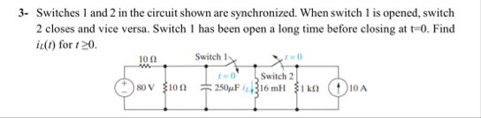 3- Switches | and 2 in the circuit shown are synchronized. When switch 11is opened, switch
2 closes and vice versa. Switch 1 has been open a long time before closing at 1-0. Find
ile) for 10.
oo | Swicki 0
SF ER