 VIPSolutions
Give step-by-step solution with explanation and final answer:Problem 6. VW R 10 A capacitor consisting of two circular conducting Rr a disks of radius R separated by a distance d was © +Q) i) initially charged and is now discharging through a — _ resistor as shown. Form the Poynting vector at a a oo point on the “boundary” of the E field, assuming no — EE fringing fields, and integrate the flux of the Poynting dd : Bp) vector through this cylindrical surface. Show that — d LL the result equals Po = ar , the rate of change of the energy stored in the capacitor.
Question:
Give step-by-step solution with explanation and final answer: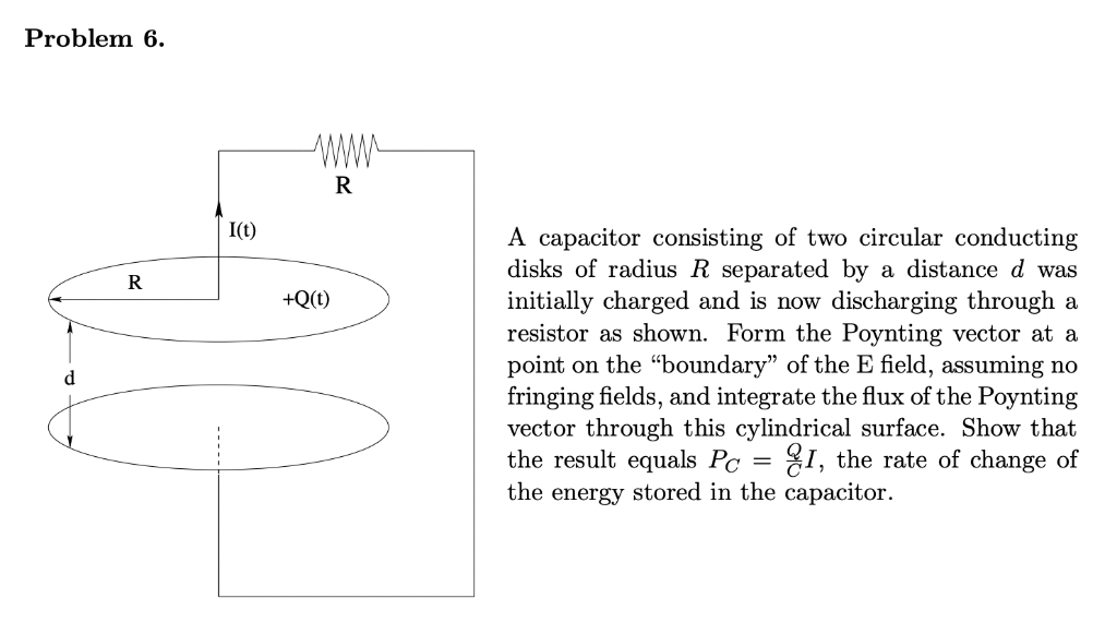 Problem 6.
VW
R
10 A capacitor consisting of two circular conducting
Rr a disks of radius R separated by a distance d was
© +Q) i) initially charged and is now discharging through a
— _ resistor as shown. Form the Poynting vector at a
a oo point on the “boundary” of the E field, assuming no
— EE fringing fields, and integrate the flux of the Poynting
dd : Bp) vector through this cylindrical surface. Show that
— d LL the result equals Po = ar , the rate of change of
the energy stored in the capacitor.
This is AI generated Response.
Asked by: gvr
Created at: 2025-07-26 03:13:41
Asked by: gvr
Created at: 2025-07-26 03:13:41
Final Answer:
Rendered
Raw Text
Did you like this answer?
Let's work through the problem step by step:
---
### **Step 1: Understanding the Problem**
We have a **capacitor** (two circular plates of radius \( R \), separated by distance \( d \)) discharging through a **resistor** \( R \). We are to:
1. Form the **Poynting vector** at the "boundary" of the electric field (i.e., at the edge of the capacitor plates).
2. Integrate the **flux** of the Poynting vector through the cylindrical surface surrounding the region between the plates.
3. Show that this flux equals the **rate of change of the energy stored in the capacitor**: \( P_C = \frac{Q}{C} I \).
---
### **Step 2: Electric and Magnetic Fields**
#### **Electric Field between the Plates**
For a parallel plate capacitor (neglecting fringing fields):
\[
E = \frac{Q}{\epsilon_0 A}
\]
where \( A = \pi R^2 \) is the area of the plates.
#### **Magnetic Field at the Edge (using Ampère's Law with Maxwell's correction)**
The displacement current between the plates is equal to the actual current in the wires:
\[
I(t) = \frac{dQ}{dt}
\]
By symmetry, the magnetic field at radius \( r = R \) (the edge) inside the capacitor is:
\[
\oint \vec{B} \cdot d\vec{l} = \mu_0 \epsilon_0 \frac{d\Phi_E}{dt}
\]
\[
B(2\pi R) = \mu_0 \epsilon_0 \frac{d}{dt}(E \cdot \pi R^2)
\]
But \( E = \frac{Q}{\epsilon_0 \pi R^2} \), so:
\[
E \cdot \pi R^2 = \frac{Q}{\epsilon_0}
\]
\[
\frac{d}{dt}(E \cdot \pi R^2) = \frac{1}{\epsilon_0} \frac{dQ}{dt} = \frac{I}{\epsilon_0}
\]
Thus,
\[
B(2\pi R) = \mu_0 I
\implies B = \frac{\mu_0 I}{2\pi R}
\]
---
### **Step 3: Poynting Vector**
The **Poynting vector** is:
\[
\vec{S} = \frac{1}{\mu_0} (\vec{E} \times \vec{B})
\]
- \( \vec{E} \) is vertically between the plates.
- \( \vec{B} \) is tangential (azimuthal) around the edge.
- \( \vec{E} \times \vec{B} \) points radially inward (through the cylindrical surface at the edge of the plates).
Magnitude:
\[
S = \frac{1}{\mu_0} E B
\]
---
### **Step 4: Surface Integral of the Poynting Flux**
The **surface** through which we want the flux is the **cylindrical surface** of radius \( R \) and height \( d \):
\[
\text{Flux} = \int \vec{S} \cdot d\vec{A} = S \times (\text{surface area})
\]
\[
\text{Area} = 2\pi R d
\]
Therefore,
\[
P = S \cdot 2\pi R d = \frac{1}{\mu_0} E B \cdot 2\pi R d
\]
Substitute in the values for \( E \) and \( B \):
- \( E = \frac{Q}{\epsilon_0 \pi R^2} \)
- \( B = \frac{\mu_0 I}{2\pi R} \)
So,
\[
P = \frac{1}{\mu_0} \left(\frac{Q}{\epsilon_0 \pi R^2}\right) \left(\frac{\mu_0 I}{2\pi R}\right) (2\pi R d)
\]
Simplify:
- \( \mu_0 \) cancels.
- \( 2\pi R \) in numerator cancels with denominator.
\[
P = \frac{Q}{\epsilon_0 \pi R^2} \cdot \frac{I}{1} \cdot d
\]
\[
P = \frac{Q I d}{\epsilon_0 \pi R^2}
\]
But recall for a parallel plate capacitor:
\[
C = \epsilon_0 \frac{\pi R^2}{d}
\implies \frac{d}{\epsilon_0 \pi R^2} = \frac{1}{C}
\]
So,
\[
P = \frac{Q I}{C}
\]
---
### **Step 5: Interpretation**
This result is exactly the **rate of change of energy stored in the capacitor**. Recall:
\[
U = \frac{1}{2} \frac{Q^2}{C}
\]
\[
\frac{dU}{dt} = \frac{Q}{C} \frac{dQ}{dt} = \frac{Q}{C} I
\]
---
### **Final Answer**
\[
\boxed{
\int \vec{S} \cdot d\vec{A} = \frac{Q}{C} I
}
\]
This is the **rate of change of energy stored in the capacitor**, as requested. The Poynting flux through the cylindrical surface surrounding the capacitor equals the power loss from the capacitor as it discharges.
📢 Instructions:
- Ask anything relatd to above question only.
- For new Question goto :