 VIPSolutions
Give step-by-step solution with explanation and final answer:(6) Two extra strain gauges with gauge factor 2.1 are added in the middle of the cantilever. The direction of the 0.6 N force is changed oppositely. The thickness and width of the cantilever are increased to 10% from their origin values. Illustrate the new arrangement of the strain gauges on the cantilever loadcell including its labelling and dimension. (5 marks) (d) Based on the new arrangement in Q2(c), find the strains, and the six resistances of each of the cantilever when it is subjected to an upward force of 0.6N. (8 marks)
Question:
Give step-by-step solution with explanation and final answer: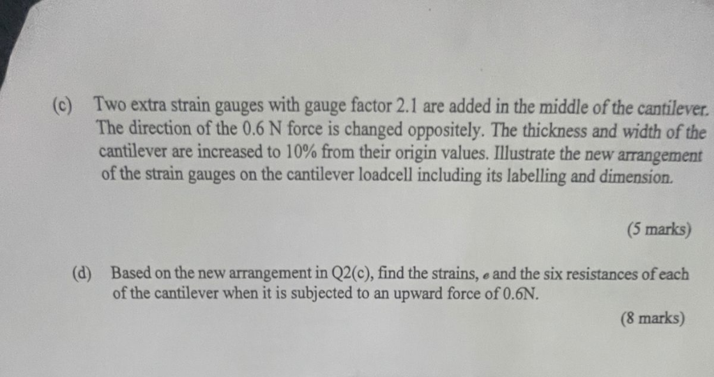 (6) Two extra strain gauges with gauge factor 2.1 are added in the middle of the cantilever.
The direction of the 0.6 N force is changed oppositely. The thickness and width of the
cantilever are increased to 10% from their origin values. Illustrate the new arrangement
of the strain gauges on the cantilever loadcell including its labelling and dimension.
(5 marks)
(d) Based on the new arrangement in Q2(c), find the strains, and the six resistances of each
of the cantilever when it is subjected to an upward force of 0.6N.
(8 marks)
This is AI generated Response.
Asked by: BIBEKANANDA ROUT
Created at: 2025-07-08 23:31:45
Asked by: BIBEKANANDA ROUT
Created at: 2025-07-08 23:31:45
Final Answer:
Rendered
Raw Text
Did you like this answer?
Let's break down and answer each part step by step.
---
### (c) **New Arrangement Illustration and Labelling**
#### **Given/Changes:**
- Two extra strain gauges (Gauge Factor = 2.1) are added in the middle of the cantilever.
- The force (0.6 N) direction is now upward (opposite).
- Thickness and width of the cantilever are increased by 10% from their original values.
- **Task:** Illustrate and label the new arrangement of the strain gauges on the cantilever (show positions and new dimensions).
#### **Step 1: Original Arrangement (Assumed)**
Assume the original cantilever had 4 strain gauges:
- 2 at the fixed end (top and bottom)
- 2 at the free end (top and bottom)
#### **Step 2: New Arrangement**
- Add 2 extra strain gauges **in the middle** (one on top surface, one on bottom surface).
#### **Step 3: New Dimensions**
If original width = \( w_0 \) and thickness = \( t_0 \), then:
- New width = \( w = w_0 \times 1.10 \)
- New thickness = \( t = t_0 \times 1.10 \)
#### **Step 4: Illustration (Text Description)**
```
|---------------------------------------------|
| |
| [SG1] [SG3] [SG5] Top surface
| |
| [SG2] [SG4] [SG6] Bottom surface
| |
|---------------------------------------------|
^Fixed end Middle Free end
```
- **SG1, SG2:** Near fixed end (top/bottom)
- **SG3, SG4:** Middle (top/bottom) -- *newly added*
- **SG5, SG6:** Near free end (top/bottom)
**Label dimensions**:
- Length = \( L \)
- Width = \( w = 1.1w_0 \)
- Thickness = \( t = 1.1t_0 \)
---
### (d) **Find Strains and Resistances**
#### **Step 1: Strain at Each Gauge Location**
The strain \( \epsilon \) in a cantilever beam under load \( F \) at a distance \( x \) from the fixed end (for a rectangular cross-section) is:
\[
\epsilon(x) = \frac{6F(L-x)}{Ewt^2}
\]
where:
- \( F \) = applied force (0.6 N)
- \( L \) = length of cantilever
- \( x \) = distance from fixed end to gauge position
- \( E \) = Young's modulus (needs to be given or assumed)
- \( w \) = width (new, \( 1.1w_0 \))
- \( t \) = thickness (new, \( 1.1t_0 \))
#### **Step 2: Positions**
Assume:
- SG1, SG2: \( x_1 = 0 \) (fixed end)
- SG3, SG4: \( x_2 = L/2 \) (middle)
- SG5, SG6: \( x_3 = L \) (free end)
Now, calculate strains:
- At fixed end: \( \epsilon_1 = \frac{6F(L-0)}{Ewt^2} = \frac{6FL}{Ewt^2} \)
- At middle: \( \epsilon_2 = \frac{6F(L-L/2)}{Ewt^2} = \frac{6F(L/2)}{Ewt^2} = \frac{3FL}{Ewt^2} \)
- At free end: \( \epsilon_3 = 0 \) (since \( L-x = 0 \))
#### **Step 3: Gauge Factor and Resistance Change**
Gauge factor \( GF \) relates strain to relative change in resistance:
\[
\frac{\Delta R}{R} = GF \cdot \epsilon
\]
- **Assume original resistance \( R_0 \) for all gauges.**
#### **Step 4: Calculate Resistance for Each Gauge**
\[
R = R_0 + \Delta R = R_0 (1 + GF \cdot \epsilon)
\]
- **At fixed end (SG1, SG2):**
\[
\epsilon_1 = \frac{6FL}{Ewt^2}
\]
\[
R_{SG1,2} = R_0 (1 + 2.1 \cdot \epsilon_1)
\]
- **At middle (SG3, SG4):**
\[
\epsilon_2 = \frac{3FL}{Ewt^2}
\]
\[
R_{SG3,4} = R_0 (1 + 2.1 \cdot \epsilon_2)
\]
- **At free end (SG5, SG6):**
\[
\epsilon_3 = 0
\]
\[
R_{SG5,6} = R_0
\]
---
### **Final Answer:**
#### (c) **Arrangement Illustration**
- Six strain gauges: 2 at fixed end (top/bottom), 2 at middle (top/bottom, newly added), 2 at free end (top/bottom).
- Dimensions: width and thickness increased by 10% (\( w = 1.1w_0, t = 1.1t_0 \)).
- SG positions: \( x_1 = 0 \), \( x_2 = L/2 \), \( x_3 = L \).
#### (d) **Strains & Resistances**
- **Strain at SG1/SG2:** \( \epsilon_1 = \frac{6FL}{Ewt^2} \)
- **Strain at SG3/SG4:** \( \epsilon_2 = \frac{3FL}{Ewt^2} \)
- **Strain at SG5/SG6:** \( \epsilon_3 = 0 \)
- **Resistance:**
- \( R_{SG1,2} = R_0 (1 + 2.1 \cdot \epsilon_1) \)
- \( R_{SG3,4} = R_0 (1 + 2.1 \cdot \epsilon_2) \)
- \( R_{SG5,6} = R_0 \)
> **To get numerical answers, you need values for \( R_0, w_0, t_0, L, E \). Plug in the numbers as needed.**
---
If you provide original dimensions or material properties, I can compute the actual values!
📢 Instructions:
- Ask anything relatd to above question only.
- For new Question goto :