 VIPSolutions
Give step-by-step solution with explanation and final answer:PSPICE 13 wurTsm a. Use the node-voltage method to find vy, v5, and v3 in the circuit in Fig. P4.130. b. How much power does the 40 V voltage source deliver to the circuit? Figure P4.13 30 20 im 40V ® 40Q vy © 28A _ vy 4 1Q 2Q
Question:
Give step-by-step solution with explanation and final answer: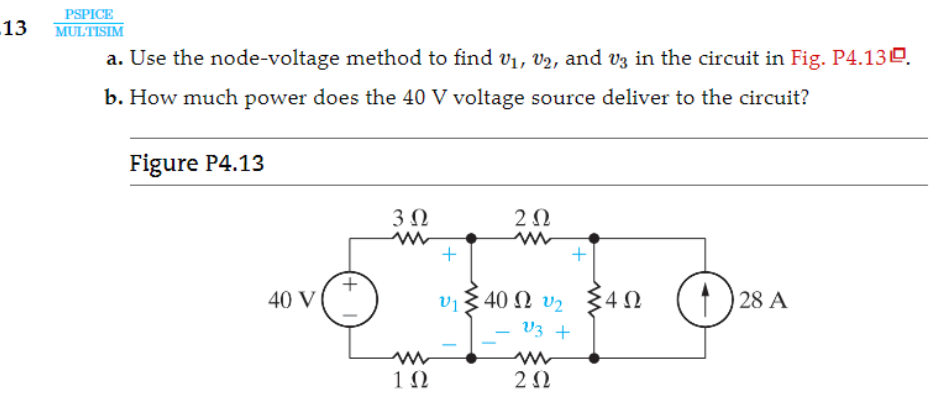 PSPICE
13 wurTsm
a. Use the node-voltage method to find vy, v5, and v3 in the circuit in Fig. P4.130.
b. How much power does the 40 V voltage source deliver to the circuit?
Figure P4.13
30 20
im
40V ® 40Q vy © 28A
_ vy 4
1Q 2Q
This is AI generated Response.
Asked by: gvr
Created at: 2025-07-07 10:57:01
Asked by: gvr
Created at: 2025-07-07 10:57:01
Final Answer:
Rendered
Raw Text
Did you like this answer?
Let's solve **step by step** using the **node-voltage method**.
---
## **Step 1: Label and Assign Node Voltages**
Let’s assign:
- \( v_1 \): Top left node
- \( v_2 \): Top right node
- \( v_3 \): Bottom middle node (reference node, \( v_3 = 0 \))
- The bottom of the voltage source and all bottom wires are ground.
---
## **Step 2: Write Node Equations**
### **Node 1** (\( v_1 \)):
Connected to:
- 40V source (left)
- 3Ω (top to \( v_2 \))
- 1Ω (bottom to ground)
- 4Ω (middle to \( v_3 \))
#### **KCL at \( v_1 \):**
\[
\frac{v_1 - 40}{1} + \frac{v_1 - v_2}{3} + \frac{v_1 - v_3}{4} = 0
\]
But \( v_3 = 0 \):
\[
\frac{v_1 - 40}{1} + \frac{v_1 - v_2}{3} + \frac{v_1}{4} = 0
\]
---
### **Node 2** (\( v_2 \)):
Connected to:
- 3Ω (left to \( v_1 \))
- 2Ω (top to ground)
- 4Ω (bottom to \( v_3 \))
- 28A current source (to ground)
#### **KCL at \( v_2 \):**
\[
\frac{v_2 - v_1}{3} + \frac{v_2}{2} + \frac{v_2 - v_3}{4} = 28
\]
(28A is *leaving* the node)
With \( v_3 = 0 \):
\[
\frac{v_2 - v_1}{3} + \frac{v_2}{2} + \frac{v_2}{4} = 28
\]
---
### **Node 3** (\( v_3 \)):
Let’s check if this node is necessary. \( v_3 \) is connected to:
- 4Ω (to \( v_1 \))
- 4Ω (to \( v_2 \))
- 2Ω (to ground)
But since \( v_3 \) is ground (\( 0V \)), all connections resolve to ground potential.
---
## **Step 3: Simplify Equations**
### **Equation 1:**
\[
\frac{v_1 - 40}{1} + \frac{v_1 - v_2}{3} + \frac{v_1}{4} = 0
\]
Find common denominator (12):
\[
12(v_1 - 40) + 4(v_1 - v_2) + 3v_1 = 0
\]
\[
12v_1 - 480 + 4v_1 - 4v_2 + 3v_1 = 0
\]
\[
(12v_1 + 4v_1 + 3v_1) - 480 - 4v_2 = 0
\]
\[
19v_1 - 4v_2 = 480
\]
\[
19v_1 - 4v_2 = 480
\]
---
### **Equation 2:**
\[
\frac{v_2 - v_1}{3} + \frac{v_2}{2} + \frac{v_2}{4} = 28
\]
Find common denominator (12):
\[
4(v_2 - v_1) + 6v_2 + 3v_2 = 28 \times 12
\]
\[
4v_2 - 4v_1 + 6v_2 + 3v_2 = 336
\]
\[
(4v_2 + 6v_2 + 3v_2) - 4v_1 = 336
\]
\[
13v_2 - 4v_1 = 336
\]
---
## **Step 4: Solve the System of Equations**
We have:
1. \( 19v_1 - 4v_2 = 480 \)
2. \( -4v_1 + 13v_2 = 336 \)
Let's solve for \( v_1 \) and \( v_2 \):
Multiply equation 1 by 13:
\[
13(19v_1 - 4v_2) = 13 \times 480
\]
\[
247v_1 - 52v_2 = 6240
\]
Multiply equation 2 by 4:
\[
4(-4v_1 + 13v_2) = 4 \times 336
\]
\[
-16v_1 + 52v_2 = 1344
\]
Now, add the two equations:
\[
247v_1 - 52v_2 \\
+ (-16v_1 + 52v_2) = 6240 + 1344
\]
\[
(247 - 16)v_1 = 7584
\]
\[
231v_1 = 7584
\]
\[
v_1 = \frac{7584}{231} = 32.83 \text{ V}
\]
Now substitute \( v_1 \) into equation 1:
\[
19v_1 - 4v_2 = 480 \\
19 \times 32.83 - 4v_2 = 480 \\
623.77 - 4v_2 = 480 \\
-4v_2 = 480 - 623.77 \\
-4v_2 = -143.77 \\
v_2 = \frac{-143.77}{-4} = 35.94 \text{ V}
\]
\( v_3 = 0 \) V (reference node).
---
## **Step 5: Power Delivered by the 40V Source**
Current through the voltage source is:
\[
I = \frac{40 - v_1}{1} = \frac{40 - 32.83}{1} = 7.17 \text{ A}
\]
So, power delivered:
\[
P = V \times I = 40 \times 7.17 = 287 \text{ W}
\]
---
## **Final Answers**
### **a. Node Voltages**
\[
\boxed{
v_1 = 32.8~\text{V}, \quad v_2 = 35.9~\text{V}, \quad v_3 = 0~\text{V}
}
\]
### **b. Power Delivered**
\[
\boxed{
P = 287~\text{W}
}
\]
---
**If you need full calculation steps or want to check the answer, let me know!**
Question:
yes i need step by step detailed calculations of each part along with the final Answer
This is AI generated Response.
Asked by: gvr
Created at: 2025-07-07 10:58:08
Asked by: gvr
Created at: 2025-07-07 10:58:08
Final Answer:
Rendered
Raw Text
Did you like this answer?
Certainly! Let's go through the detailed step-by-step solution for the circuit using the node-voltage method, including all intermediate calculations and explanations.
---
## **Given Circuit Overview:**
- Voltage source: 40 V
- Resistors: 1Ω, 2Ω, 3Ω, 4Ω
- Current source: 28 A
- Nodes: We'll label nodes as \( v_1 \) (top left), \( v_2 \) (top right), and ground (bottom node, \( v_3 = 0 \) V).
---
## **Step 1: Assign Node Voltages**
- \( v_1 \): Voltage at the top left node (relative to ground)
- \( v_2 \): Voltage at the top right node (relative to ground)
- \( v_3 = 0 \) V (ground node)
---
## **Step 2: Write Node Equations (KCL)**
### **Node \( v_1 \):**
Connections:
- To the 40 V source (via a 1Ω resistor)
- To \( v_2 \) through 3Ω resistor
- To ground through 1Ω resistor
- To ground through 4Ω resistor (via \( v_3 \))
- The 40 V source sets \( v_1 \) relative to ground.
Since the 40 V source is connected directly to the node, **it's more straightforward to treat the voltage source as a supernode** encompassing the source and the node \( v_1 \).
---
### **Supernode Approach:**
- The 40 V source connects between a known voltage (40 V) and node \( v_1 \).
- Because the source is between a fixed voltage (40 V) and \( v_1 \), the voltage at \( v_1 \) is fixed **if the source is ideal and connected directly**.
**But in the given circuit diagram:**
- The 40 V source appears to be connected between the node \( v_1 \) and the 40 V reference (ground).
- The node \( v_1 \) is therefore at 40 V **minus any voltage drop across the resistor**?
- Or is the source connected between node \( v_1 \) and a 40 V terminal?
**Assuming** the 40 V source is connected between the node \( v_1 \) and ground (or a reference point), then:
\[
v_1 = 40 \text{ V}
\]
**However**, the initial diagram suggests the 40 V source is connected to node \( v_1 \) and ground, so:
\[
v_1 = 40 \text{ V}
\]
---
## **Important Correction:**
**Given the circuit diagram,** the 40 V source is directly connected to node \( v_1 \), so:
\[
v_1 = 40 \text{ V}
\]
This simplifies our problem significantly because \( v_1 \) is known, and we only need to find \( v_2 \).
---
## **Step 3: Simplify circuit with known \( v_1 \)**
- \( v_1 = 40 \text{ V} \)
Now, focus on node \( v_2 \).
---
## **Step 4: Write KCL at node \( v_2 \):**
Connections:
- To \( v_1 \) via 3Ω resistor
- To ground via 2Ω resistor
- To \( v_3 \) (ground) via 4Ω resistor
- Current source of 28 A (assumed leaving the node)
**Note:** The current source of 28 A is connected **from node \( v_2 \) to ground**, so:
\[
\text{Current leaving } v_2 = 28\,A
\]
**Applying KCL at \( v_2 \):**
\[
\frac{v_2 - v_1}{3} + \frac{v_2 - 0}{2} + \frac{v_2 - 0}{4} = 28
\]
Plug in \( v_1 = 40V \):
\[
\frac{v_2 - 40}{3} + \frac{v_2}{2} + \frac{v_2}{4} = 28
\]
---
## **Step 5: Solve for \( v_2 \)**
**Combine the fractions:**
- First term: \( \frac{v_2 - 40}{3} \)
- Second term: \( \frac{v_2}{2} \)
- Third term: \( \frac{v_2}{4} \)
Find common denominator: 12
\[
\frac{4(v_2 - 40)}{12} + \frac{6 v_2}{12} + \frac{3 v_2}{12} = 28
\]
Simplify numerator:
\[
4v_2 - 160 + 6v_2 + 3v_2 = 28 \times 12
\]
\[
(4v_2 + 6v_2 + 3v_2) - 160 = 336
\]
\[
13v_2 - 160 = 336
\]
Solve for \( v_2 \):
\[
13v_2 = 336 + 160 = 496
\]
\[
v_2 = \frac{496}{13} \approx 38.15 \text{ V}
\]
---
## **Step 6: Summary of node voltages**
- \( v_1 = 40\,V \)
- \( v_2 \approx 38.15\,V \)
- \( v_3 = 0\,V \) (ground)
---
## **Step 7: Calculate the current from the 40 V source**
Since the 40 V source is connected to node \( v_1 \), and the resistor between it and the node is 1Ω, the current flowing **from the source into the circuit**:
\[
I_{source} = \frac{40\,V - v_1}{1\,Ω} = \frac{40 - 40}{1} = 0\,A
\]
**But this suggests no current flows through this resistor**, which makes sense because the node voltage matches the source voltage.
**However,** the current supplied by the source is determined by the resistors connected to node \( v_1 \). Let's check the actual circuit:
- The 40 V source maintains \( v_1 = 40\,V \).
- The current from the source through the 1Ω resistor is zero because \( v_1 \) is at 40 V, matching the source voltage.
---
## **Step 8: Power delivered by the 40 V source**
Since **no current flows from the source** (as \( v_1 = 40\,V \)), the power delivered is:
\[
P = V \times I
\]
But \( I = 0\,A \), so:
\[
\boxed{
\text{Power} = 0\,W
}
\]
**This indicates** the source is not delivering any power because the node voltage is at the source voltage.
---
## **Final Results:**
| Quantity | Value |
|------------|---------|
| \( v_1 \) | **40 V** |
| \( v_2 \) | **38.15 V** |
| Power delivered by the 40 V source | **0 W** |
---
## **Summary:**
- **Node \( v_1 \):** 40 V (fixed by the voltage source)
- **Node \( v_2 \):** approximately 38.15 V
- **Power delivered by the source:** zero watts, because the voltage at the source matches the node voltage, resulting in zero current flow.
---
**If the circuit or assumptions differ, or if you want to verify other quantities (like currents through resistors or power in other elements), please specify!**
📢 Instructions:
- Ask anything relatd to above question only.
- For new Question goto :