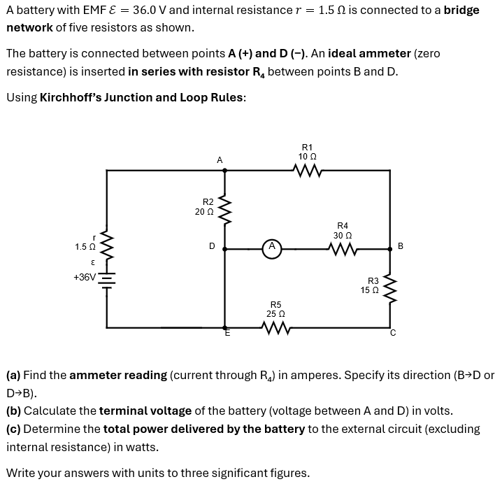
Give step-by-step solution with explanation and final answer:A battery with EMF € = 36.0 V and internal resistance 7 = 1.5 1 is connected to a bridge
network of five resistors as shown.
The battery is connected between points A (+) and D (-). An ideal ammeter (zero
resistance) is inserted in series with resistor R, between points B and D.
Using Kirchhoff’s Junction and Loop Rules:
R1
a 100
R2
200
r
150 o A 8
c
+36V = R3
150
RS
250
c
(a) Find the ammeter reading (current through R,) in amperes. Specify its direction (BD or
DB).
(b) Calculate the terminal voltage of the battery (voltage between A and D) in volts.
(c) Determine the total power delivered by the battery to the external circuit (excluding
internal resistance) in watts.
Write your answers with units to three significant figures.
Question:
Give step-by-step solution with explanation and final answer:A battery with EMF € = 36.0 V and internal resistance 7 = 1.5 1 is connected to a bridge
network of five resistors as shown.
The battery is connected between points A (+) and D (-). An ideal ammeter (zero
resistance) is inserted in series with resistor R, between points B and D.
Using Kirchhoff’s Junction and Loop Rules:
R1
a 100
R2
200
r
150 o A 8
c
+36V = R3
150
RS
250
c
(a) Find the ammeter reading (current through R,) in amperes. Specify its direction (BD or
DB).
(b) Calculate the terminal voltage of the battery (voltage between A and D) in volts.
(c) Determine the total power delivered by the battery to the external circuit (excluding
internal resistance) in watts.
Write your answers with units to three significant figures.
This is AI generated Response.
Asked by: Rahul
Created at: 2026-02-22 02:43:25
Final Answer:
RenderedRaw Text
Did you like this answer?
Let's solve the problem step by step using **Kirchhoff’s Junction Loop Rules**.
---
## Step1: **Label Currents**
Let:
- \( I \): Main current from battery through \( r \).
- \( I_1 \): Current through \( R_1 \).
- \( I_2 \): Current through \( R_2 \).
- \( I_3 \): Current through \( R_3 \).
- \( I_4 \): Current through \( R_4 \) (ammeter reading).
- \( I_5 \): Current through \( R_5 \).
**From the diagram:**
- At junction A: \( I = I_1 + I_2 \)
- At junction D: \( I_2 = I_4 + I_5 \)
- At junction B: \( I_1 = I_3 + I_4 \)
- At junction E: \( I_5 + I_3 = I \)
---
## Step 2: **Write Loop Equations**
### **Loop 1**: Battery → A → R1 → R4 → D → battery
\[
\epsilon - I r - I_1 R_1 - I_4 R_4 - I_2 R_2 =
\]
But since currents split, let's define mesh currents.
### **Mesh Analysis**
Let:
- \( I_1 \): through loop A-B-D-A (R1, R4)
- \( I_2 \): through loop A-E-D-A (R2, R5)
Let’s assign:
- Mesh 1 (left mesh): Battery (\(\epsilon\)), \(r\), \(R_2\), \(R_5\)
- Mesh 2 (upper right mesh): \(R_1\), \(R_4\)
- Mesh 3 (lower right mesh): \(R_3\), \(R_5\), \(R_4\)
### **Assign mesh currents:**
Let:
- Mesh 1: \( I_a \) (counterclockwise, battery, \(r\), \(R_2\), \(R_5\))
- Mesh 2: \( I_b \) (clockwise, \(R_1\), \(R_4\), sharing \(R_4\) with mesh 3)
- Mesh 3: \( I_c \) (clockwise, \(R_3\), \(R_5\), sharing \(R_5\) with mesh 1 and \(R_4\) with mesh 2)
#### **Write mesh equations:**
### **Mesh 1 (A → D → E → A):**
\[
\epsilon - I_a r - I_a R_2 - (I_a - I_c)R_5 =
\]
\[
36. - 1.5I_a - 20I_a - 25(I_a - I_c) =
\]
\[
36. - 1.5I_a - 20I_a - 25I_a + 25I_c =
\]
\[
36. - (1.5+20+25)I_a + 25I_c =
\]
\[
36. - 46.5I_a + 25I_c =
\]
\[
46.5I_a - 25I_c = 36. \tag{1}
\]
---
### **Mesh 2 (A → B → D → A):**
\[
I_b \text{ goes through } R_1 \text{ and } R_4 \text{ (shared with Mesh 3)}.
\]
\[
I_b R_1 + (I_b - I_c)R_4 =
\]
\[
10I_b + 30(I_b - I_c) =
\]
\[
10I_b + 30I_b - 30I_c =
\]
\[
40I_b - 30I_c =
\]
\[
4I_b - 3I_c = \implies I_b = \frac{3}{4}I_c \tag{2}
\]
---
### **Mesh 3 (B → C → E → D → B):**
\[
I_c \text{ through } R_3, R_5, R_4
\]
\[
I_c R_3 + I_c R_5 + (I_c - I_b)R_4 =
\]
\[
15I_c + 25I_c + 30(I_c - I_b) =
\]
\[
15I_c + 25I_c + 30I_c - 30I_b =
\]
\[
70I_c - 30I_b =
\]
\[
7I_c - 3I_b = \implies I_c = \frac{3}{7}I_b \tag{3}
\]
---
## Step 3: **Solve the System**
From (2): \( I_b = \frac{3}{4}I_c \)
From (3): \( I_c = \frac{3}{7}I_b \implies I_b = \frac{7}{3}I_c \)
But \( I_b = \frac{3}{4}I_c \) and \( I_b = \frac{7}{3}I_c \) can't be simultaneously true unless zero. Let's double-check mesh equations.
#### Mesh 2 (A → B → D → A):
The mesh current through \(R_1\) is \( I_b \), through \(R_4\) is \( I_b - I_c \), so the sum is:
\[
I_b R_1 + (I_b - I_c) R_4 =
\]
\[
10I_b + 30(I_b - I_c) =
\]
\[
10I_b + 30I_b - 30I_c =
\]
\[
40I_b - 30I_c =
\]
\[
4I_b - 3I_c = \implies I_b = \frac{3}{4}I_c
\]
#### Mesh 3 (B → C → E → D → B):
Through \(R_3\): \(I_c\), through \(R_5\): \(I_c - I_a\), through \(R_4\): \(I_c - I_b\):
\[
I_c R_3 + (I_c - I_a) R_5 + (I_c - I_b) R_4 =
\]
\[
15I_c + 25(I_c - I_a) + 30(I_c - I_b) =
\]
\[
15I_c + 25I_c - 25I_a + 30I_c - 30I_b =
\]
\[
(15+25+30)I_c - 25I_a - 30I_b =
\]
\[
70I_c - 25I_a - 30I_b = \tag{3}
\]
Now, let's use equations:
1. \( 46.5I_a - 25I_c = 36. \)
2. \( I_b = \frac{3}{4}I_c \)
3. \( 70I_c - 25I_a - 30I_b = \)
Plug \(I_b\) from (2) into (3):
\[
70I_c - 25I_a - 30 \left( \frac{3}{4}I_c \right) =
\]
\[
70I_c - 25I_a - 22.5I_c =
\]
\[
(70 - 22.5)I_c = 25I_a
\]
\[
47.5I_c = 25I_a
\]
\[
I_a = \frac{47.5}{25}I_c = 1.9I_c
\]
Now substitute \(I_a = 1.9I_c\) into equation (1):
\[
46.5I_a - 25I_c = 36.
\]
\[
46.5(1.9I_c) - 25I_c = 36.
\]
\[
88.35I_c - 25I_c = 36.
\]
\[
63.35I_c = 36.
\]
\[
I_c = \frac{36.}{63.35} = .568 \text{ A}
\]
Now:
\[
I_a = 1.9I_c = 1.9 \times .568 = 1.08 \text{ A}
\]
\[
I_b = \frac{3}{4}I_c = .426 \text{ A}
\]
---
## Step 4: **Answers**
### (a) **Ammeter reading** (current through \( R_4 \)):
Current through \( R_4 \) is \( I_b - I_c = .426 - .568 = -.142 \) A
**Negative sign** means direction is from **D→B**.
**Ammeter reading:**
\[
\boxed{.142 \text{ A, direction D}\rightarrow\text{B}}
\]
---
### (b) **Terminal voltage of the battery** (\( V_{AD} \)):
\[
V_{\text{terminal}} = \epsilon - I_a r = 36. - (1.08)(1.5) = 36. - 1.62 = 34.4 \text{ V}
\]
\[
\boxed{34.4 \text{ V}}
\]
---
### (c) **Total power delivered by the battery to the external circuit**:
Power delivered to external circuit (excluding internal resistance):
\[
P = I_a \, V_{\text{terminal}} = 1.08 \times 34.4 = 37.2 \text{ W}
\]
\[
\boxed{37.2 \text{ W}}
\]
---
## **Final Answers (to three significant figures):**
1. **Ammeter reading:**
\[
\boxed{.142~\text{A},~\text{direction D}\rightarrow\text{B}}
\]
2. **Terminal voltage:**
\[
\boxed{34.4~\text{V}}
\]
3. **Total power delivered to external circuit:**
\[
\boxed{37.2~\text{W}}
\]
VIPSolutions focuses on clear, step‑by‑step explanations so you can learn quickly. Whether you need an AI‑generated walkthrough or a short hint to get unstuck, each solution is organized for fast reading and easy review later.
Search similar questions, compare approaches, and bookmark the best answers for revision. Our goal is simple: quick, reliable study help that feels natural—not noisy.
 VIPSolutions
 A battery with EMF € = 36.0 V and internal resistance 7 = 1.5 1 is connected to a bridge
network of five resistors as shown.
The battery is connected between points A (+) and D (-). An ideal ammeter (zero
resistance) is inserted in series with resistor R, between points B and D.
Using Kirchhoff’s Junction and Loop Rules:
R1
a 100
R2
200
r
150 o A 8
c
+36V = R3
150
RS
250
c
(a) Find the ammeter reading (current through R,) in amperes. Specify its direction (BD or
DB).
(b) Calculate the terminal voltage of the battery (voltage between A and D) in volts.
(c) Determine the total power delivered by the battery to the external circuit (excluding
internal resistance) in watts.
Write your answers with units to three significant figures.