 VIPSolutions
Give step-by-step solution with explanation and final answer:FE = CB 20 Bizure P20 shows a total gas force F applied to the top of a piston. = ~ a Copy the drawing and sketch the force paths through the piston, through the piston pin, and into the connecting rod. ~ b. Making appropriate simplifving assumptions, identify the stresses in the piston pin and write an equation for each._ State the assumptions made, and discuss briefly their effect. = = = Total gas force = F = = — — = = — ea Eel = Fire 2———ve—a— ¥ ==. = 4 = | EEE — i Nii —— = ol = Pl — = - = _—
Question:
Give step-by-step solution with explanation and final answer: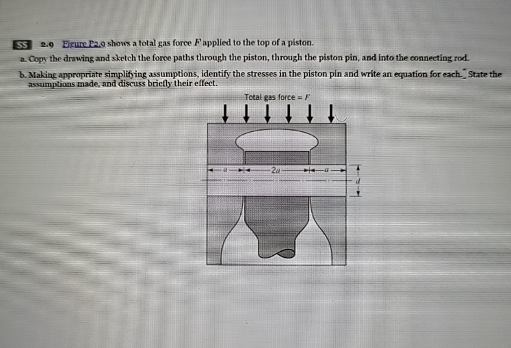 FE =
CB 20 Bizure P20 shows a total gas force F applied to the top of a piston. =
~ a Copy the drawing and sketch the force paths through the piston, through the piston pin, and into the connecting rod.
~ b. Making appropriate simplifving assumptions, identify the stresses in the piston pin and write an equation for each._ State the
assumptions made, and discuss briefly their effect. =
= = Total gas force = F = =
— — =
= — ea Eel =
Fire 2———ve—a— ¥
==. = 4
= | EEE
— i Nii ——
= ol = Pl —
= - = _—
This is AI generated Response.
Asked by: Alok Kumar
Created at: 2026-01-25 06:15:57
Asked by: Alok Kumar
Created at: 2026-01-25 06:15:57
Final Answer:
Rendered
Raw Text
Did you like this answer?
# Step-by-Step Solution
## a. Copy the Drawing and Sketch Force Paths
**Description of Force Paths:**
1. **Gas Force on Piston:**
The total gas force \( F \) is applied vertically down on the top of the piston.
2. **Force Transfer through Piston:**
This force is transmitted downwards through the body of the piston.
3. **Force on Piston Pin:**
The force then acts on the piston pin (the horizontal cylindrical pin shown) at both sides.
4. **Force into Connecting Rod:**
The piston pin transmits the force into the connecting rod, which is connected at the middle of the pin.
**Force Path Sketch (Described):**
- Draw arrows from the top of the piston downward.
- Show the force splitting and transferring horizontally onto the piston pin (on both sides).
- Indicate the force being carried through the pin toward the center (where the connecting rod is attached).
- Show the force then proceeding downward through the connecting rod.
---
## b. Stresses in the Piston Pin & Equations
### **Simplifying Assumptions:**
- The force \( F \) is evenly distributed on both sides of the piston pin.
- The pin is simply supported at both ends and loaded at the center by the connecting rod.
- The pin is assumed to be uniform and the contact is perfectly rigid.
### **Identification of Stresses:**
#### 1. **Shear Stress in the Pin**
- **Cause:** The vertical force from the piston is transferred to the pin at both sides; the connecting rod pulls down at the center.
- **Shear force at the center:**
\[
\tau = \frac{F}{A}
\]
Where \( A = \pi d^2 / 4 \) is the cross-sectional area of the pin (if loaded in pure shear at the center).
#### 2. **Bending Stress in the Pin**
- **Cause:** The pin acts as a simply supported beam, loaded at the center by the force \( F \).
- **Maximum bending moment at the center:**
\[
M_{\text{max}} = \frac{F \cdot l}{4}
\]
Where \( l = 2a \) (the distance between supports, i.e., the width of the piston).
- **Bending stress:**
\[
\sigma_{\text{bending}} = \frac{M_{\text{max}} \cdot c}{I}
\]
Where:
- \( c = d/2 \) (distance from neutral axis to outer fiber)
- \( I = \frac{\pi d^4}{64} \) (moment of inertia of circular cross-section)
Substitute values:
\[
\sigma_{\text{bending}} = \frac{M_{\text{max}} \cdot (d/2)}{\frac{\pi d^4}{64}} = \frac{F \cdot l \cdot d}{8 \cdot \frac{\pi d^4}{64}}
= \frac{F \cdot l \cdot 64}{8 \pi d^3}
= \frac{8 F l}{\pi d^3}
\]
If \( l = 2a \):
\[
\sigma_{\text{bending}} = \frac{8 F (2a)}{\pi d^3} = \frac{16 F a}{\pi d^3}
\]
---
### **Summary of Equations:**
- **Shear Stress:**
\[
\tau = \frac{F}{\pi d^2 / 4} = \frac{4F}{\pi d^2}
\]
- **Maximum Bending Stress:**
\[
\sigma_{\text{bending}} = \frac{16 F a}{\pi d^3}
\]
---
### **Assumptions and Their Effects:**
- **Uniform Load Distribution:** Real contact may cause stress concentrations; results are idealized.
- **Rigid Supports:** Actual supports may deform, causing more complex stress patterns.
- **Neglecting Pin Deflection:** If the pin is long or heavily loaded, deflection could increase stresses.
---
## **Final Answer**
### **a. Force Paths:**
- Force goes from gas → piston → piston pin (at both sides) → connecting rod.
### **b. Stresses & Equations:**
- **Shear stress:** \( \tau = \frac{4F}{\pi d^2} \)
- **Bending stress:** \( \sigma_{\text{bending}} = \frac{16 F a}{\pi d^3} \)
- **Assumptions:** Uniform load, rigid supports, neglecting deflection.
Let me know if you need the force path sketch or more details!
📢 Instructions:
- Ask anything relatd to above question only.
- For new Question goto :