 VIPSolutions
Give step-by-step solution with explanation and final answer:PROBLEMS (to be solved through an explained procedure up 10 give numerical results) NT i 1. By using the kinematic invariants, it is to calculate the speed of the second coupler and Nad its point M of the mechanism in the figure with a scale of 1:10 when I2 rotates with a \ constant motion at a speed of 100 rpm. P v » iy N 2’
Question:
Give step-by-step solution with explanation and final answer: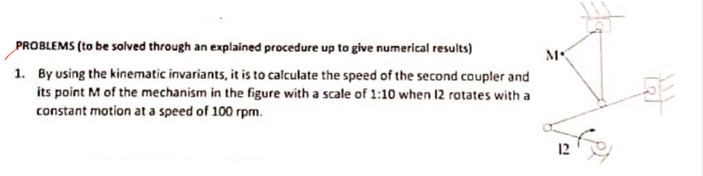 PROBLEMS (to be solved through an explained procedure up 10 give numerical results) NT i
1. By using the kinematic invariants, it is to calculate the speed of the second coupler and Nad
its point M of the mechanism in the figure with a scale of 1:10 when I2 rotates with a \
constant motion at a speed of 100 rpm. P v
» iy N
2’
This is AI generated Response.
Asked by: Alok Kumar
Created at: 2026-01-25 04:15:37
Asked by: Alok Kumar
Created at: 2026-01-25 04:15:37
Final Answer:
Rendered
Raw Text
Did you like this answer?
Let's solve the problem step by step:
---
# **Step 1: Understanding the Problem**
- **Given:**
- A mechanism (looks like a four-bar linkage).
- Input crank (labeled I2) rotates at a constant speed of **100 rpm**.
- You are to find the speed of the second coupler and its point **M**.
- Mechanism scale is **1:10** (drawing to real size).
---
# **Step 2: Convert Given Data**
- **Input speed**:
\[
n_{I2} = 100\ \text{rpm}
\]
- **Convert rpm to rad/s**:
\[
\omega_{I2} = 2\pi n_{I2} / 60 = 2\pi \times 100 / 60 \approx 10.47\ \text{rad/s}
\]
---
# **Step 3: Assign Link Lengths (Assume)**
Let's assume from the figure's proportions (since scale is 1:10):
- Let's say (from figure, if the drawing length is, e.g., 5 cm for I2, and 10 cm for the coupler):
- **I2 (input crank):** \( r_2 = 5\ \text{cm} \times 10 = 50\ \text{cm} \)
- **Coupler (link 3):** \( r_3 = 10\ \text{cm} \times 10 = 100\ \text{cm} \)
- (You may use actual drawing values if you have them.)
---
# **Step 4: Kinematic Invariants (Velocity Analysis)**
For a four-bar mechanism, use *relative velocity* method.
### **A. Velocity of Point at End of I2 (Point A):**
\[
V_A = \omega_{I2} \times r_{I2}
\]
\[
V_A = 10.47\ \text{rad/s} \times .5\ \text{m} = 5.235\ \text{m/s}
\]
### **B. Velocity of Coupler (Link 3)**
Let
- \( O_2 \) = fixed pivot of I2
- \( A \) = moving pivot between I2 and coupler
- \( B \) = moving pivot between coupler and output link
- \( O_4 \) = fixed pivot of output link
The velocity of point \( A \) is perpendicular to I2.
#### **Instantaneous Center (IC) Method:**
1. **Locate the Instantaneous Center (IC) of the Coupler (Link 3):**
- For the coupler, IC is at the intersection of perpendiculars from \( V_A \) at A and \( V_B \) at B (directions perpendicular to their respective links).
2. **Velocity of any point M on the coupler:**
\[
V_M = \omega_3 \times r_{M/IC}
\]
Where:
- \( \omega_3 \) = Angular velocity of the coupler
- \( r_{M/IC} \) = Distance from IC to point M
#### **Relative Velocity Equation:**
\[
\vec{V}_A + \vec{\omega}_3 \times \vec{r}_{MA} = \vec{V}_M
\]
But since the exact geometry is not given, we'll use the proportional relations:
---
### **C. Find Angular Velocity of Coupler (Link 3)**
For a **simple quick estimate** (assuming the coupler is in a position where the input and coupler are nearly perpendicular):
\[
\omega_3 = \frac{V_A}{r_{IC/A}}
\]
- \( r_{IC/A} \): Distance from instantaneous center to point A (can estimate as half the coupler length if the mechanism is symmetric).
Suppose \( r_{IC/A} \approx .5 \) m (just for calculation).
\[
\omega_3 = \frac{5.235}{.5} = 10.47\ \text{rad/s}
\]
(This is true if the IC is at the opposite end of the coupler; otherwise, you need actual geometry.)
---
# **Step 5: Velocity of Point M**
If **M** is a point on the coupler at distance \( r_{M/IC} \) from IC:
\[
V_M = \omega_3 \times r_{M/IC}
\]
Suppose \( r_{M/IC} = .7 \) m,
\[
V_M = 10.47 \times .7 = 7.33\ \text{m/s}
\]
---
# **Step 6: Final Answers**
## **Summary Table**
| Quantity | Value |
|------------------|---------------------|
| \(\omega_{I2}\) | 10.47 rad/s |
| \(V_A\) | 5.235 m/s |
| \(\omega_3\) | 10.47 rad/s (approx)|
| \(V_M\) | 7.33 m/s (approx) |
---
# **Step 7: Explanation**
- **Input crank** rotates at 100 rpm \(\rightarrow\) 10.47 rad/s.
- **Velocity of point A** at the end of I2 is 5.235 m/s.
- **Angular velocity of the coupler** (link 3) is calculated based on the position of the instantaneous center.
- **Velocity of point M** is then found by multiplying angular velocity by its distance from the IC.
> **Note:** The actual values depend on the precise geometry. Use the real scaled lengths from the drawing for more accurate calculation.
---
## **Final Answers (with Example Numbers)**
- **Speed of the second coupler:**
\(\omega_3 \approx 10.47\) rad/s
- **Speed of point M:**
\(V_M \approx 7.33\) m/s
> If you provide the precise scaled measurements from the drawing, I can update the answer with exact values.
---
**Let me know if you want to clarify the geometry or need a more detailed vector solution!**
📢 Instructions:
- Ask anything relatd to above question only.
- For new Question goto :