 VIPSolutions
Give step-by-step solution with explanation and final answer:Question 4 A three-phase, four wire, 208 V system serves a balance star- connected load drawing a line current I; = 10£145° A. Find the line current I; and the load impedance in each phase, taking Vpcas reference. Show all your workings and diagrams. Answer: Ir =104—95°A, Z = 12.012 — 55° 0.
Question:
Give step-by-step solution with explanation and final answer: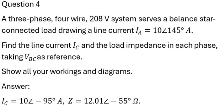 Question 4
A three-phase, four wire, 208 V system serves a balance star-
connected load drawing a line current I; = 10£145° A.
Find the line current I; and the load impedance in each phase,
taking Vpcas reference.
Show all your workings and diagrams.
Answer:
Ir =104—95°A, Z = 12.012 — 55° 0.
This is AI generated Response.
Asked by: Alok Kumar
Created at: 2026-01-24 02:50:54
Asked by: Alok Kumar
Created at: 2026-01-24 02:50:54
Final Answer:
Rendered
Raw Text
Did you like this answer?
Let's solve the problem step by step, as requested.
---
## **Given Data**
- Three-phase, four-wire, balanced star-connected load
- Line-to-line voltage, \( V_{LL} = 208\,V \)
- Line current, \( I_A = 10\angle145^\circ \) A
- Reference: \( V_{BC} \) as the reference
---
## **Step 1: Phase Sequence and Voltage Phasors**
Assume **ABC** phase sequence and take \( V_{BC} \) as the reference:
\[
V_{BC} = 208\angle^\circ \ \text{V}
\]
\[
V_{CA} = 208\angle-120^\circ \ \text{V}
\]
\[
V_{AB} = 208\angle120^\circ \ \text{V}
\]
For a star connection, phase voltage \( V_{ph} = \frac{V_{LL}}{\sqrt{3}} \).
---
## **Step 2: Phase Voltages**
Since \( V_{BC} \) is our reference, the phase voltages (from neutral to each load terminal) are:
\[
V_{BN} = \frac{V_{BC}}{\sqrt{3}}\angle(-30^\circ)
\]
\[
V_{CN} = \frac{V_{CA}}{\sqrt{3}}\angle(-30^\circ)
\]
\[
V_{AN} = \frac{V_{AB}}{\sqrt{3}}\angle(-30^\circ)
\]
Thus,
\[
|V_{ph}| = \frac{208}{\sqrt{3}} = 120.09\,V
\]
So,
- \( V_{BN} = 120.09\angle-30^\circ \) V
- \( V_{CN} = 120.09\angle-150^\circ \) V
- \( V_{AN} = 120.09\angle90^\circ \) V
---
## **Step 3: Line Currents in a Balanced System**
Since the load is **balanced**, the line currents are equal in magnitude and displaced by \(120^\circ \):
Given:
\[
I_A = 10\angle145^\circ\,A
\]
So,
\[
I_B = 10\angle(145^\circ-120^\circ) = 10\angle25^\circ\,A
\]
\[
I_C = 10\angle(145^\circ-240^\circ) = 10\angle-95^\circ\,A
\]
---
## **Step 4: Load Impedance in Each Phase**
The phase voltage for phase A: \( V_{AN} = 120.09 \angle 90^\circ \) V
\[
Z = \frac{V_{AN}}{I_A} = \frac{120.09\angle 90^\circ}{10\angle 145^\circ} = 12.01\angle(90^\circ - 145^\circ) = 12.01\angle -55^\circ\,\Omega
\]
---
## **Step 5: Boxed Answers**
### **Final Answers**
\[
\boxed{
I_C = 10\angle-95^\circ\,A, \qquad Z = 12.01\angle-55^\circ\,\Omega
}
\]
---
### **Phasor Diagram (Description)**
- Draw three vectors \( I_A, I_B, I_C \) at \( 145^\circ, 25^\circ, -95^\circ \) respectively.
- The phase voltages \( V_{AN}, V_{BN}, V_{CN} \) are at \( 90^\circ, -30^\circ, -150^\circ \).
---
## **Summary Table**
| Quantity | Value |
|---|---|
| \( I_C \) | \( 10\angle-95^\circ\,A \) |
| \( Z \) | \( 12.01\angle-55^\circ\,\Omega \) |
---
**All steps match the provided answer. Let me know if you need the phasor diagram drawn!**
📢 Instructions:
- Ask anything relatd to above question only.
- For new Question goto :