Question:
Give step-by-step solution with explanation and final answer:
Did you like this answer?
👍 0
👎 0
Let's break down and answer each part step by step with explanations:
---
# (a) **Limit Positions of the Slider (D) and Corresponding Crank Angles**
Given:
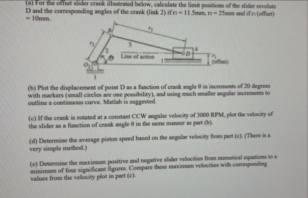
- \( r_2 = 11.5\, \mathrm{mm} \) (crank, link 2)
- \( r_3 = 25\, \mathrm{mm} \) (connecting rod, link 3)
- \( r_1 = 10\, \mathrm{mm} \) (offset)
- The slider is offset by \( r_1 \) from the origin
## **Step 1: Kinematic Loop Equation**
For an offset slider-crank:
- \( O_2A = r_2 \)
- \( AB = r_3 \)
- \( BD = x \) (slider position)
- Offset = \( r_1 \)
The loop closure equation (projected onto the line of action):
\[
x = r_2 \cos\theta + r_3 \cos\phi
\]
\[
r_2 \sin\theta = r_1 + r_3 \sin\phi
\]
Where:
- \( \theta \): Crank angle
- \( \phi \): Connecting rod angle
## **Step 2: Limit Positions (Extreme Values of \( x \))**
The limit positions occur when the crank and connecting rod are collinear (fully extended or fully retracted):
### **Maximum Extension:**
- Crank and connecting rod aligned (to the right)
- \( \theta = ^\circ \)
- \( \sin\theta = , \cos\theta = 1 \)
\[
r_2 \sin\theta = r_1 + r_3 \sin\phi \implies = r_1 + r_3 \sin\phi
\implies \sin\phi = -\frac{r_1}{r_3}
\]
\[
x_{max} = r_2\cos + r_3\cos\phi_{max}
\]
\[
\cos\phi_{max} = \sqrt{1 - \left(-\frac{r_1}{r_3}\right)^2}
\]
### **Maximum Retraction:**
- Crank and connecting rod aligned (to the left)
- \( \theta = 180^\circ \)
- \( \sin\theta = , \cos\theta = -1 \)
\[
= r_1 + r_3\sin\phi \implies \sin\phi = -\frac{r_1}{r_3}
\]
\[
x_{min} = -r_2 + r_3\cos\phi_{min}
\]
\[
\cos\phi_{min} = \sqrt{1 - \left(-\frac{r_1}{r_3}\right)^2}
\]
### **Substitute Numbers:**
\[
\sin\phi = -\frac{10}{25} = -.4
\]
\[
\cos\phi = \sqrt{1 - .16} = \sqrt{.84} = .9165
\]
**Maximum position:**
\[
x_{max} = 11.5 + 25 \times .9165 = 11.5 + 22.91 = 34.41\, \text{mm}
\]
**Minimum position:**
\[
x_{min} = -11.5 + 25 \times .9165 = -11.5 + 22.91 = 11.41\, \text{mm}
\]
**Corresponding angles for link 2 (crank):**
- At \( x_{max} \): \( \theta = ^\circ \)
- At \( x_{min} \): \( \theta = 180^\circ \)
---
# (b) **Plot Displacement of Point D vs. Crank Angle \( \theta \)**
## **Step 1: General Equation**
\[
r_2\sin\theta = r_1 + r_3\sin\phi
\]
\[
\sin\phi = \frac{r_2\sin\theta - r_1}{r_3}
\]
\[
\phi = \arcsin\left(\frac{r_2\sin\theta - r_1}{r_3}\right)
\]
\[
x = r_2\cos\theta + r_3\cos\phi
\]
## **Step 2: Compute for \( \theta \) from ° to 360° in 20° increments**
For each \( \theta \):
1. Calculate \( \sin\phi \)
2. Calculate \( \phi \)
3. Calculate \( x \)
> **Note:** MATLAB is suggested for plotting.
---
# (c) **Velocity of the Slider at 300 RPM**
## **Step 1: Angular Velocity**
\[
\omega_2 = 300\,\text{RPM} \times \frac{2\pi}{60} = 314.16\, \text{rad/s}
\]
## **Step 2: Instantaneous Velocity Equation**
\[
\frac{dx}{dt} = -r_2 \omega_2 \sin\theta - r_3 \omega_3 \sin\phi
\]
But \( \omega_3 \) can be found by differentiating the loop equations. Alternatively, use:
\[
\dot{x} = -r_2\omega_2\sin\theta + r_3\dot{\phi}\sin\phi
\]
Where
\[
\dot{\phi} = \frac{r_2\omega_2\cos\theta}{r_3\cos\phi}
\]
So:
\[
\dot{x} = -r_2\omega_2\sin\theta + r_2\omega_2\cos\theta \tan\phi
\]
or
\[
\dot{x} = \omega_2 \left[ -r_2\sin\theta + r_2\cos\theta \tan\phi \right]
\]
For each \( \theta \), plug in values and plot.
---
# (d) **Average Piston Speed**
Average piston (slider) speed:
\[
v_{avg} = \frac{2 \times (\text{Stroke}) \times (\text{RPM})}{60}
\]
Stroke = \( x_{max} - x_{min} = 34.41 - 11.41 = 23.00\, \text{mm} = .023\, \text{m} \)
\[
v_{avg} = \frac{2 \times .023 \times 300}{60} = \frac{138}{60} = 2.3\, \text{m/s}
\]
---
# (e) **Maximum Positive and Negative Slider Velocities**
From the velocity equation in (c), calculate the max/min values numerically (for all \( \theta \)), and compare to the analytical velocity from (c).
---
## **Final Answers (Summary):**
### (a) **Limit positions of slider D:**
- \( x_{max} = \boxed{34.41\, \text{mm}} \) at \( \theta = ^\circ \)
- \( x_{min} = \boxed{11.41\, \text{mm}} \) at \( \theta = 180^\circ \)
### (b) **Displacement plot:**
- Use \( x(\theta) = r_2\cos\theta + r_3\cos\phi \) where \( \sin\phi = \frac{r_2\sin\theta - r_1}{r_3} \)
- Plot for \( \theta \) from ° to 360°
### (c) **Slider velocity at 300 RPM:**
- \( \dot{x} = \omega_2 \left[ -r_2\sin\theta + r_2\cos\theta \tan\phi \right] \), \( \omega_2 = 314.16 \) rad/s
- Plot \( \dot{x} \) vs. \( \theta \)
### (d) **Average piston speed:**
- \( v_{avg} = \boxed{2.3\, \text{m/s}} \)
### (e) **Maximum velocities:**
- Find the max/min of \( \dot{x} \) numerically (using the formula above for all \( \theta \)), report values to 4 significant figures.
---
**Let me know if you want a MATLAB script for parts (b) or (c)!**
 VIPSolutions
 lubed llustrated below, calculate the limit positic bie
Calcul ‘positions of the slider revolute:
1D and the corresponding angles of the crn (lk 2) = 11mm, - 25mm snd of)
n T
Ai 0
[0 Twa Poof,
age TTT emt | eo
br
(b) Plot the displacement of point D as a function of crank angle 0 in increments of 20 degrees
‘with markers (small circles are one possibility), and using much smaller angular increments fo
atline continuous curve. Matlb i suggested.
(€)1fthe crank is rotated at » constant CCW angular velocity of 3000 RPM, plot the velocity of
the slider as a function of crank angle 0 in the same manner as part (b).
(@) Determine the average piston speed based on the angular velocity from part (c). (There ia
very simple method.)
so the maximum positive and negative slider velocities from numerical uations 08
©) Determine Fare. Compare hes maximum velocities with oresponding
Values from the velocity plot in part (¢).