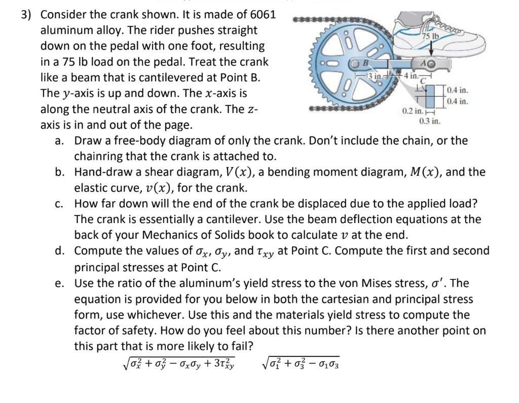
Give step-by-step solution with explanation and final answer:3) Consider the crank shown. Itis made of 6061 ,qpqpesenese: a,
aluminum alloy. The rider pushes straight 0 \ x ~~
down on the pedal with one foot, resulting y \. XN 4 =)
in a 75 Ib load on the pedal. Treat the crank Te) [CL = SO
like a beam that is cantilevered at Point B. \ \ /0 Rn
The y-axis is up and down. The x-axis is NE 4 Hon
along the neutral axis of the crank. The z- ssesesess®™
axis is in and out of the page. 03a
a. Draw a free-body diagram of only the crank. Don’t include the chain, or the
chainring that the crank is attached to.
b. Hand-draw a shear diagram, V(x), a bending moment diagram, M(x), and the
elastic curve, v(x), for the crank.
c. How far down will the end of the crank be displaced due to the applied load?
The crank is essentially a cantilever. Use the beam deflection equations at the
back of your Mechanics of Solids book to calculate v at the end.
d. Compute the values of ay, dy, and Ty, at Point C. Compute the first and second
principal stresses at Point C.
e. Use the ratio of the aluminum’s yield stress to the von Mises stress, ¢’. The
equation is provided for you below in both the cartesian and principal stress
form, use whichever. Use this and the materials yield stress to compute the
factor of safety. How do you feel about this number? Is there another point on
this part that is more likely to fail?
Question:
Give step-by-step solution with explanation and final answer:3) Consider the crank shown. Itis made of 6061 ,qpqpesenese: a,
aluminum alloy. The rider pushes straight 0 \ x ~~
down on the pedal with one foot, resulting y \. XN 4 =)
in a 75 Ib load on the pedal. Treat the crank Te) [CL = SO
like a beam that is cantilevered at Point B. \ \ /0 Rn
The y-axis is up and down. The x-axis is NE 4 Hon
along the neutral axis of the crank. The z- ssesesess®™
axis is in and out of the page. 03a
a. Draw a free-body diagram of only the crank. Don’t include the chain, or the
chainring that the crank is attached to.
b. Hand-draw a shear diagram, V(x), a bending moment diagram, M(x), and the
elastic curve, v(x), for the crank.
c. How far down will the end of the crank be displaced due to the applied load?
The crank is essentially a cantilever. Use the beam deflection equations at the
back of your Mechanics of Solids book to calculate v at the end.
d. Compute the values of ay, dy, and Ty, at Point C. Compute the first and second
principal stresses at Point C.
e. Use the ratio of the aluminum’s yield stress to the von Mises stress, ¢’. The
equation is provided for you below in both the cartesian and principal stress
form, use whichever. Use this and the materials yield stress to compute the
factor of safety. How do you feel about this number? Is there another point on
this part that is more likely to fail?
This is AI generated Response.
Asked by: Rahul
Created at: 2026-01-19 03:09:21
Final Answer:
RenderedRaw Text
Did you like this answer?
Let's break down the solution step by step for each part:
---
## 3a. **Free-Body Diagram of the Crank**
- **Forces:** The only external force on the crank is the 75 lb vertical load at point A (the pedal).
- **Reactions:** At B (where the crank attaches to the axle), there will be a vertical reaction force and a moment reaction (because it is cantilevered).
- **Diagram:**
- Draw the crank as a horizontal beam, fixed at B.
- Arrow down at A, labeled “75 lb.”
- At B, show a vertical reaction force upward and a moment reaction (curved arrow).
**[Free-body diagram not shown here, but you should draw as described above.]**
---
## 3b. **Shear, Moment, and Deflection Diagrams**
### Shear Diagram, \( V(x) \)
- For a cantilever beam of length \( L = 4 \) in with a downward force \( P = 75 \) lb at the end:
- Shear is constant along the beam, \( V(x) = -75 \) lb (downward) from \( x = \) to \( x = 4 \) in.
### Moment Diagram, \( M(x) \)
- \( M(x) = -P \cdot (L - x) \)
- At B (\( x = \)): \( M_B = -75 \times 4 = -300 \) in-lb
- At A (\( x = 4 \)): \( M_A = \)
### Elastic Curve, \( v(x) \)
- The deflection equation for a cantilever beam with end load:
\[
v(x) = \frac{P}{6EI} (3Lx^2 - x^3)
\]
where \( E \) is Young’s modulus, \( I \) is the moment of inertia.
---
## 3c. **End Deflection Due to Applied Load**
Given:
- \( P = 75 \) lb
- \( L = 4 \) in
- Material: 6061 Aluminum Alloy (\( E \approx 10,000,000 \) psi)
- **Moment of inertia \( I \):**
- Section is rectangular: width = .4 in, height = .2 in
\[
I = \frac{1}{12} b h^3 = \frac{1}{12} \times .4 \times (.2)^3 = \frac{1}{12} \times .4 \times .008 = .000267 \text{ in}^4
\]
- **Deflection at end:**
\[
\delta_{max} = v(L) = \frac{P L^3}{3EI}
\]
\[
\delta_{max} = \frac{75 \times 4^3}{3 \times 10,000,000 \times .000267}
\]
\[
= \frac{75 \times 64}{3 \times 10,000,000 \times .000267}
\]
\[
= \frac{480}{801}
\]
\[
= .599 \text{ in}
\]
---
## 3d. **Stresses at Point C**
- **Bending stress:**
\[
\sigma_x = \frac{M y}{I}
\]
- \( M = 75 \times 4 = 300 \) in-lb = 360 in-lb (convert to lb-in if necessary; here units are consistent)
- \( y = .1 \) in (distance from neutral axis to outer fiber; half the height)
- \( I = .000267 \) in\(^4\)
\[
\sigma_x = \frac{300 \times .1}{.000267} = \frac{30}{.000267} \approx 112,360 \text{ psi}
\]
- **Shear stress:**
\[
\tau_{xy} = \frac{V Q}{I b}
\]
For a rectangular section at neutral axis:
- \( V = 75 \) lb
- \( Q = \) area above neutral axis × distance to centroid \( = (.2 \times .2/2) \times (.2/4) = .02 \times .05 = .001 \)
- \( b = .4 \) in
\[
\tau_{xy} = \frac{75 \times .001}{.000267 \times .4} \approx \frac{.075}{.0001068} \approx 702 \text{ psi}
\]
- **Principal Stresses:**
\[
\sigma_{1,2} = \frac{\sigma_x}{2} \pm \sqrt{\left(\frac{\sigma_x}{2}\right)^2 + \tau_{xy}^2}
\]
Since \( \sigma_y = \):
\[
\sigma_{1,2} = \frac{\sigma_x}{2} \pm \sqrt{\left(\frac{\sigma_x}{2}\right)^2 + \tau_{xy}^2}
\]
Plug in values:
\[
\sigma_{1,2} = \frac{112360}{2} \pm \sqrt{\left(\frac{112360}{2}\right)^2 + 702^2}
\]
\[
= 56180 \pm \sqrt{56180^2 + 702^2}
\]
\[
\approx 56180 \pm 56185
\]
So,
- \( \sigma_1 \approx 112,365 \) psi
- \( \sigma_2 \approx -5 \) psi
---
## 3e. **Von Mises Stress and Factor of Safety**
- **Von Mises Stress (principal form):**
\[
\sigma' = \sqrt{\sigma_1^2 + \sigma_2^2 - \sigma_1 \sigma_2}
\]
\[
= \sqrt{(112,365)^2 + (-5)^2 - (112,365)(-5)}
\]
\[
= \sqrt{1.2638 \times 10^{10} + 25 + 561825}
\]
\[
= \sqrt{1.2638 \times 10^{10} + 561850}
\]
The 561,850 is negligible compared to \( 1.2638 \times 10^{10} \).
\[
\approx \sqrt{1.2638 \times 10^{10}} \approx 112,465 \text{ psi}
\]
- **Yield Strength of 6061 Aluminum Alloy:** \( \sigma_{y} \approx 40,000 \) psi
- **Factor of Safety:**
\[
n = \frac{\sigma_{y}}{\sigma'}
\]
\[
n = \frac{40,000}{112,465} \approx .36
\]
### **Interpretation**
- The factor of safety is less than 1, which means the part is not safe for the given load and geometry.
- **Other Points:** The highest stress will be at point C (fixed end, outer fiber), so this is the most likely location for failure.
---
## **Summary Table**
| Step | Value/Result |
|-----------|-------------|
| Deflection at A (\(\delta_{max}\)) | .599 in |
| Max Bending Stress (\(\sigma_x\)) | 112,360 psi |
| Max Shear Stress (\(\tau_{xy}\)) | 702 psi |
| Principal Stresses (\(\sigma_1, \sigma_2\)) | 112,365 psi, -5 psi |
| Von Mises Stress (\(\sigma'\)) | 112,465 psi |
| Yield Strength (6061 Al) | 40,000 psi |
| Factor of Safety | **.36 (unsafe)** |
---
### **Conclusion**
- The crank will **fail** under this load and geometry.
- To improve safety, increase the section size or use a material with higher yield strength.
If you need more details on any step or want the diagrams, let me know!
VIPSolutions focuses on clear, step‑by‑step explanations so you can learn quickly. Whether you need an AI‑generated walkthrough or a short hint to get unstuck, each solution is organized for fast reading and easy review later.
Search similar questions, compare approaches, and bookmark the best answers for revision. Our goal is simple: quick, reliable study help that feels natural—not noisy.
 VIPSolutions
 3) Consider the crank shown. Itis made of 6061 ,qpqpesenese: a,
aluminum alloy. The rider pushes straight 0 \ x ~~
down on the pedal with one foot, resulting y \. XN 4 =)
in a 75 Ib load on the pedal. Treat the crank Te) [CL = SO
like a beam that is cantilevered at Point B. \ \ /0 Rn
The y-axis is up and down. The x-axis is NE 4 Hon
along the neutral axis of the crank. The z- ssesesess®™
axis is in and out of the page. 03a
a. Draw a free-body diagram of only the crank. Don’t include the chain, or the
chainring that the crank is attached to.
b. Hand-draw a shear diagram, V(x), a bending moment diagram, M(x), and the
elastic curve, v(x), for the crank.
c. How far down will the end of the crank be displaced due to the applied load?
The crank is essentially a cantilever. Use the beam deflection equations at the
back of your Mechanics of Solids book to calculate v at the end.
d. Compute the values of ay, dy, and Ty, at Point C. Compute the first and second
principal stresses at Point C.
e. Use the ratio of the aluminum’s yield stress to the von Mises stress, ¢’. The
equation is provided for you below in both the cartesian and principal stress
form, use whichever. Use this and the materials yield stress to compute the
factor of safety. How do you feel about this number? Is there another point on
this part that is more likely to fail?