 VIPSolutions
Give step-by-step solution with explanation and final answer:Problem # 2: Produce two views for the part. Indicate the cutting plane in the front view and develop the front view as half-sectional view. Material is Cast Iron. ETN yrs 09) or mois > aN “2 PL) NN 91> \ N17 = (N10 vo (NY NA] em Ny A Ni NYA am fix NG) as Problem #3: The font and top view of an object is shown blow. Sketch thse views asi i on .25 in square grid sheet, indicate the cuuting plane on the top view and develop an offset frontal sectional view, Capture as amany features as you can. Material is Brass.
Question:
Give step-by-step solution with explanation and final answer: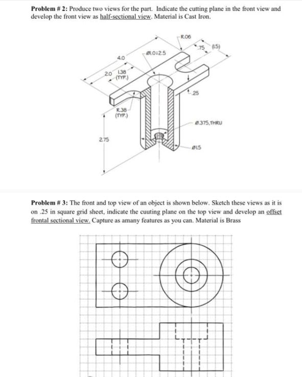 Problem # 2: Produce two views for the part. Indicate the cutting plane in the front view and
develop the front view as half-sectional view. Material is Cast Iron.
ETN
yrs 09)
or mois > aN
“2
PL)
NN 91>
\ N17
= (N10
vo (NY
NA] em
Ny A
Ni
NYA
am fix
NG) as
Problem #3: The font and top view of an object is shown blow. Sketch thse views asi i
on .25 in square grid sheet, indicate the cuuting plane on the top view and develop an offset
frontal sectional view, Capture as amany features as you can. Material is Brass.
This is AI generated Response.
Asked by: Rahul
Created at: 2026-01-17 02:38:34
Asked by: Rahul
Created at: 2026-01-17 02:38:34
Final Answer:
Rendered
Raw Text
Did you like this answer?
Let's break down the solution for both problems step-by-step:
---
# **Problem #2: Half-Sectional View Drawing (Cast Iron Part)**
## **Step 1: Understanding the Part**
- The part is a cylindrical base with arms extending from it and several holes and fillets.
- The front view will show the main shape, and the top view will show the arms and holes.
## **Step 2: Indicate the Cutting Plane**
- The cutting plane should pass vertically through the center of the part, cutting through the axis, showing internal details on one half.
## **Step 3: Draw the Top View**
- **Outline:** Draw the large central circle (Ø2.5).
- **Arms:** Draw the arms extending out at 90° intervals.
- **Holes:** Mark the central hole (Ø.375) and any other holes visible from the top.
## **Step 4: Draw the Front View (Half-Section)**
- **Left Half:** Show the external features—outline, arms, external fillets.
- **Right Half (Sectioned Side):**
- Show the internal details: central hole, stepped features, internal fillets.
- Use section lining (hatching) for the areas cut by the plane.
- **Indicate the Cutting Plane:** In the top view, draw a bold dashed line showing where the half-section is taken.
## **Step 5: Final Answer Illustration**
Here’s a **simplified sketch** for clarity (not to scale):
```
Top View (with cutting plane AA):
______________________
| |
| ________ |
| | | |
|---| |--- |
| | | |
|___|________|_________|
/ (O) \
(Central Circle)
Front View (half-sectioned):
_______
| |<-- Left half: external
| |<-- Right half: sectioned (show internal features and hatch)
| |
|_______|
```
- Use hatching on the right half to indicate sectioned material.
- Mark hole positions and internal features clearly.
---
# **Problem #3: Offset Frontal Sectional View (Brass Part)**
## **Step 1: Analyze Views**
- The grid shows both the top and front views.
- The top view has two small circles (holes) and a large central circle.
## **Step 2: Indicate Offset Cutting Plane**
- On the top view, draw a bold line (cutting plane) that passes through both holes and the center of the large circle, making "offset" turns to include all features.
## **Step 3: Develop Offset Frontal Sectional View**
- **Project features from the top and front views to the section view.**
- **Show internal details revealed by the offset plane:**
- The two smaller holes will be visible as open circles.
- The large central hole will be visible in section.
- **Use hatching** to indicate material cut by the plane.
## **Step 4: Sketch the Views on Grid**
- **Top View:** As provided, with the cutting plane marked.
- **Front View:** Draw as provided.
- **Offset Sectional View (frontal):**
- Use the grid to project features down.
- Draw hidden/internal features as solid lines in the section.
- Hatch areas that are cut.
## **Final Answer Illustration**
(Simplified, not to scale)
```
Top View (with offset cutting plane AA):
___________________
| ___ ___ |
| | | | | |
|---| |---| |---|
| | | | | |
|___|___|___|___|___|
Cutting plane: __/----\____ through both holes and center.
Offset Sectional View:
___________________
| | | | | |
| Hatching for cut |
| Holes shown open |
| Internal details |
| | | | | |
```
- Use hatching and solid lines as appropriate.
---
## **Summary Table**
| Problem | View Type | Cutting Plane | Sectional Features |
|---------|-------------------|----------------------|------------------------------------|
| #2 | Half-sectional | Vertical, center | Shows internal hole, fillets, arms |
| #3 | Offset-frontal | Offset, through holes| Shows holes, center, hatching |
---
**If you need a hand-drawn or digital sketch, let me know!**
📢 Instructions:
- Ask anything relatd to above question only.
- For new Question goto :