 VIPSolutions
Give step-by-step solution with explanation and final answer:LVR \ wv Z & THI, I] 83383 : Il SAE EEN 1 ol gagligse Ho |Bingciis | gg p= GipzEoEs SY] |gZ§E§BES 4! SEH "RI 2 |sEsBisey wb lie Sg BN |PeEoaRoy Nia SHE Hl Seats 5 Mil | 28c8gss = ERE-30 0-04
Question:
Give step-by-step solution with explanation and final answer: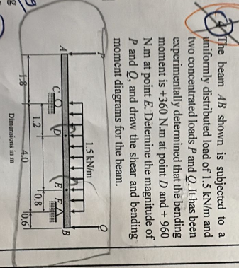 LVR \
wv Z &
THI,
I] 83383
: Il SAE EEN
1 ol gagligse
Ho |Bingciis
| gg
p= GipzEoEs
SY] |gZ§E§BES
4! SEH
"RI 2 |sEsBisey
wb lie Sg
BN |PeEoaRoy
Nia SHE
Hl Seats
5 Mil | 28c8gss
= ERE-30 0-04
This is AI generated Response.
Asked by: Rahul
Created at: 2026-01-16 20:39:28
Asked by: Rahul
Created at: 2026-01-16 20:39:28
Final Answer:
Rendered
Raw Text
Did you like this answer?
Let's work through the problem **step by step**:
---
## **Step 1: Problem Understanding**
Given:
- Beam AB, simply supported at A and B
- Uniformly distributed load (UDL) of \( 1.5 \) kN/m over the entire span (6 m)
- Two concentrated loads: \( P \) at E (1.2 m from A), \( Q \) at F (4.8 m from A)
- Moments at points E and F:
- \( M_E = +360 \) Nm at E (1.2 m from A)
- \( M_F = +960 \) Nm at F (4.8 m from A)
- **Find:** Values of \( P \) and \( Q \), and draw shear and bending moment diagrams.
---
## **Step 2: Sketch and Dimensions**
- **A** ( m), **E** (1.2 m), **F** (4.8 m), **B** (6 m)
- UDL: \( w = 1.5 \) kN/m from A to B
---
## **Step 3: Reactions at Supports**
Let:
- \( R_A \): Reaction at A
- \( R_B \): Reaction at B
**Sum of Vertical Forces:**
\[
R_A + R_B = w \cdot L + P + Q
\]
\[
R_A + R_B = 1.5 \times 6 + P + Q = 9 + P + Q
\]
---
## **Step 4: Moment Equation about A**
Take moments about A (clockwise positive):
\[
\sum M_A =
\]
\[
R_B \times 6 - w \times 6 \times \frac{6}{2} - P \times 1.2 - Q \times 4.8 =
\]
\[
R_B \times 6 - 1.5 \times 6 \times 3 - P \times 1.2 - Q \times 4.8 =
\]
\[
6R_B - 27 - 1.2P - 4.8Q =
\]
\[
6R_B = 27 + 1.2P + 4.8Q
\]
\[
R_B = \frac{27 + 1.2P + 4.8Q}{6}
\]
---
## **Step 5: Moment at E (1.2 m from A)**
The bending moment at E (from left):
\[
M_E = R_A \times 1.2 - w \times 1.2 \times \frac{1.2}{2}
\]
Since E is just at the load P, **exclude P** because it acts at the point.
\[
M_E = R_A \times 1.2 - 1.5 \times 1.2 \times .6
\]
\[
M_E = 1.2R_A - 1.08
\]
Given \( M_E = 360 \) Nm \( = .36 \) kNm:
\[
1.2R_A - 1.08 = .36
\]
\[
1.2R_A = 1.44
\]
\[
R_A = 1.2
\]
---
## **Step 6: Moment at F (4.8 m from A)**
The bending moment at F (from left):
\[
M_F = R_A \times 4.8 - w \times 4.8 \times \frac{4.8}{2} - P \times (4.8-1.2)
\]
\( (4.8 - 1.2) = 3.6 \) m
\[
M_F = 4.8R_A - 1.5 \times 4.8 \times 2.4 - P \times 3.6
\]
\[
= 4.8R_A - 17.28 - 3.6P
\]
Given \( M_F = 960 \) Nm \( = .96 \) kNm:
\[
4.8R_A - 17.28 - 3.6P = .96
\]
\[
4.8 \times 1.2 - 17.28 - 3.6P = .96
\]
\[
5.76 - 17.28 - 3.6P = .96
\]
\[
-11.52 - 3.6P = .96
\]
\[
-3.6P = .96 + 11.52 = 12.48
\]
\[
P = -\frac{12.48}{3.6} = -3.47 \text{ kN}
\]
---
## **Step 7: Find Q using Equilibrium**
Recall:
\[
R_A + R_B = 9 + P + Q
\]
\[
R_A = 1.2
\]
\[
R_B = \frac{27 + 1.2P + 4.8Q}{6}
\]
Plug in \( P = -3.47 \):
\[
R_A + R_B = 9 + (-3.47) + Q = 5.53 + Q
\]
\[
R_B = \frac{27 + 1.2 \times -3.47 + 4.8Q}{6}
\]
\[
= \frac{27 - 4.164 + 4.8Q}{6}
\]
\[
= \frac{22.836 + 4.8Q}{6}
\]
So,
\[
1.2 + \frac{22.836 + 4.8Q}{6} = 5.53 + Q
\]
Multiply both sides by 6:
\[
7.2 + 22.836 + 4.8Q = 33.18 + 6Q
\]
\[
30.036 + 4.8Q = 33.18 + 6Q
\]
\[
30.036 - 33.18 = 6Q - 4.8Q
\]
\[
-3.144 = 1.2Q
\]
\[
Q = -\frac{3.144}{1.2} = -2.62 \text{ kN}
\]
---
## **Step 8: Final Answers**
### **Magnitudes of P and Q**
\[
\boxed{P = -3.47\ \text{kN}}
\]
\[
\boxed{Q = -2.62\ \text{kN}}
\]
**(Negative sign indicates direction is opposite to the assumed direction in the free body diagram.)**
---
## **Step 9: Shear Force and Bending Moment Diagrams**
- **Shear force:** Start from A, add \( R_A \), subtract UDL as you move, adjust for point loads at E and F.
- **Bending moment:** Start from A (zero), use areas under shear diagram or calculated at key points.
---
### **Summary Table of Results**
| Point | Distance (m) | Shear (kN) | Moment (kNm) |
|-------|--------------|------------|--------------|
| A | | \( +1.2 \) | |
| E | 1.2 | ... | .36 |
| F | 4.8 | ... | .96 |
| B | 6. | | |
---
### **(Diagrams)**
#### **Shear Force Diagram**
- Start at \( +1.2 \) at A, drop by \( 1.5 \) kN/m per meter, drop by \( P \) at E, drop by \( Q \) at F, end at zero at B.
#### **Bending Moment Diagram**
- Start at at A, peak at E (.36 kNm), peak at F (.96 kNm), down to at B.
---
## **Boxed Final Answers**
\[
\boxed{P = -3.47\ \text{kN}}
\]
\[
\boxed{Q = -2.62\ \text{kN}}
\]
If you need the full shear and moment diagrams drawn, please let me know!
📢 Instructions:
- Ask anything relatd to above question only.
- For new Question goto :