 VIPSolutions
Give step-by-step solution with explanation and final answer:1. Conduct fluid analysis of the air flow passing through an S-pipe. Assume nonslip boundary conditions along the pipe walls and the air is at a room temperature of 25°C. The velocity of the air is 5 mm/s at the inlet and the outlet is at atmospheric pressure. Determine the pressure and velocity distributions of the interior flow field. All dimensions are in millimeters. R5000 § i - 40.000 -20.000 3.000, T R10.000 Outlet 00 " i \ R10.000 i { Inlet. i 20.000: i :
Question:
Give step-by-step solution with explanation and final answer: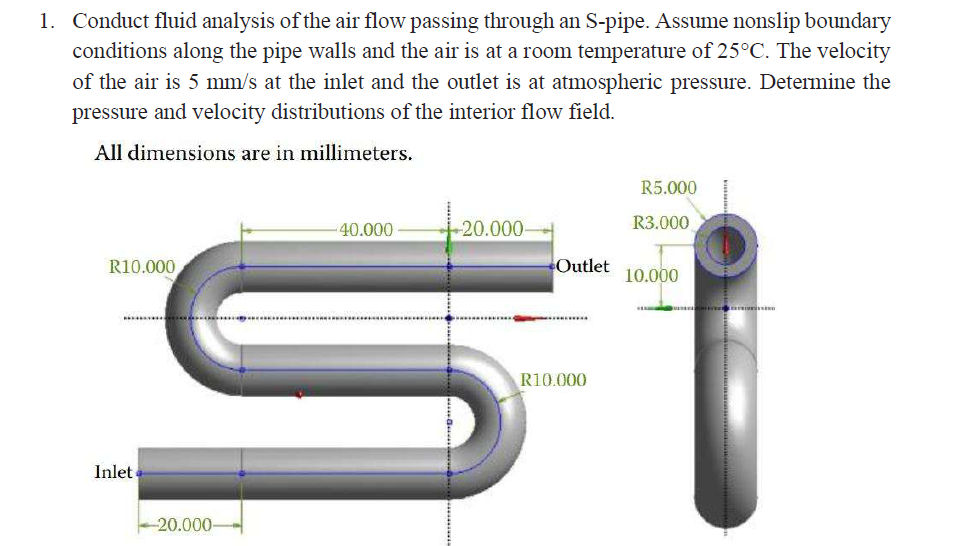 1. Conduct fluid analysis of the air flow passing through an S-pipe. Assume nonslip boundary
conditions along the pipe walls and the air is at a room temperature of 25°C. The velocity
of the air is 5 mm/s at the inlet and the outlet is at atmospheric pressure. Determine the
pressure and velocity distributions of the interior flow field.
All dimensions are in millimeters.
R5000 §
i -
40.000 -20.000 3.000,
T
R10.000 Outlet 00
" i
\ R10.000
i
{
Inlet.
i
20.000: i :
This is AI generated Response.
Asked by: Rahul
Created at: 2026-01-13 15:16:30
Asked by: Rahul
Created at: 2026-01-13 15:16:30
Final Answer:
Rendered
Raw Text
Did you like this answer?
Let's break down the **fluid analysis of air flow through the S-pipe** step by step.
---
## **Step 1: Problem Recap and Assumptions**
- **Pipe shape**: S-pipe, smooth bends.
- **Air at 25°C** (room temp).
- **Pipe diameter**: Inner radius = 3 mm ⟹ diameter = 6 mm.
- **Inlet velocity**: \( V_{inlet} = 5 \) mm/s \( = .005 \) m/s.
- **Outlet**: Atmospheric pressure.
- **Boundary condition**: No-slip at wall.
- **All dimensions**: mm (convert to meters if needed).
---
## **Step 2: Properties of Air at 25°C**
- **Density (\(\rho\))**: ~1.184 kg/m³
- **Dynamic Viscosity (\(\mu\))**: \(1.849 \times 10^{-5}\) kg/(m·s)
---
## **Step 3: Area and Flow Rate Calculation**
### **Pipe Cross-sectional Area (A):**
\[
A = \pi r^2 = \pi \times (.003)^2 = 2.827 \times 10^{-5} \text{ m}^2
\]
### **Volumetric Flow Rate (Q):**
\[
Q = V_{inlet} \times A = .005 \times 2.827 \times 10^{-5} = 1.4135 \times 10^{-7} \text{ m}^3/\text{s}
\]
---
## **Step 4: Reynolds Number Calculation**
\[
Re = \frac{\rho V D}{\mu}
\]
\[
D = 2r = .006 \text{ m}
\]
\[
Re = \frac{1.184 \times .005 \times .006}{1.849 \times 10^{-5}} = \frac{3.552 \times 10^{-5}}{1.849 \times 10^{-5}} \approx 1.92
\]
- **Flow Regime:** \(Re < 230\) ⟹ **Laminar flow**
---
## **Step 5: Velocity Distribution**
For a **laminar flow in a pipe**, the velocity profile is **parabolic**:
\[
u(r) = u_{max} \left[1 - \left(\frac{r}{R}\right)^2 \right]
\]
Where:
- \(u_{max} = 2 \times u_{avg}\)
- \(u_{avg} = V_{inlet} = .005 \) m/s
- \(R = .003\) m
So,
\[
u_{max} = 2 \times .005 = .01 \text{ m/s}
\]
\[
u(r) = .01 \left[1 - \left(\frac{r}{.003}\right)^2 \right]
\]
---
## **Step 6: Pressure Drop Calculation**
For **laminar flow**, pressure drop (\(\Delta P\)) in a straight pipe:
\[
\Delta P = \frac{8 \mu L Q}{\pi r^4}
\]
### **Total Length (L):**
- From the diagram, let's estimate:
- Horizontal: \(20+40+20 = 80\) mm
- 2 bends, each \(\approx \pi \times 10\) mm = \(31.42\) mm per bend \(= 62.84\) mm
- Total \(L \approx 80 + 62.84 = 142.84\) mm \(= .14284\) m
### **Plug values:**
\[
\Delta P = \frac{8 \times 1.849 \times 10^{-5} \times .14284 \times 1.4135 \times 10^{-7}}{\pi \times (.003)^4}
\]
Calculate denominator:
\[
\pi \times (.003)^4 = \pi \times 8.1 \times 10^{-11} = 2.545 \times 10^{-10}
\]
Calculate numerator:
\[
8 \times 1.849 \times 10^{-5} \times .14284 \times 1.4135 \times 10^{-7} \approx 2.981 \times 10^{-12}
\]
So,
\[
\Delta P = \frac{2.981 \times 10^{-12}}{2.545 \times 10^{-10}} \approx .0117 \text{ Pa}
\]
**This is a very small pressure drop due to the very low velocity and small pipe size.**
---
## **Step 7: Effects of Bends**
- For very **low Reynolds number**, losses due to bends are negligible compared to viscous (frictional) losses.
- At higher velocities, you’d add **minor losses** using loss coefficients, but for \(Re \sim 2\), you can ignore.
---
## **Step 8: Final Answers**
### **Velocity Distribution**
- **Parabolic profile**, with centerline (max) velocity:
- \(u_{max} = .01\) m/s at center
- \(u = \) m/s at wall (no-slip)
- **Formula:** \(u(r) = .01 \left[1 - \left(\frac{r}{.003}\right)^2 \right]\) (for \(r\) from to .003 m)
### **Pressure Distribution**
- **Pressure drops by \(.012\) Pa** (rounded) from inlet to outlet.
- If outlet is atmospheric, **inlet pressure = atmospheric + .012 Pa**
---
## **Summary Table**
| Parameter | Value |
|------------------------|----------------------|
| Inlet Velocity | .005 m/s |
| Max Velocity (Center) | .01 m/s |
| Reynolds Number | 1.92 (laminar flow) |
| Pressure Drop (\(\Delta P\)) | .012 Pa |
| Velocity Profile | Parabolic |
---
### **Interpretation**
- The flow is extremely slow and dominated by viscous effects.
- The pressure drop is negligible.
- The velocity profile is parabolic, as expected for laminar pipe flow.
---
**If you need velocity/pressure plots or more details, please specify!**
📢 Instructions:
- Ask anything relatd to above question only.
- For new Question goto :