 VIPSolutions
Give step-by-step solution with explanation and final answer:ERIN 15E yl TION 2 (ISOMETRIC VIEW) b wo views below are drawn in 1st angle orthogranpic oe. panatosn isonet Drawing! of he ike a 0 ere? os in the direction of the dicated a De § £211 Gite dots nol require, row indicated onthe font view anu Lo Se. ; | %_ gi = he = be | lh a | LE TN teat Lo 2 _ | El 3 x EL Sl | | i (5 . i sie fal Ew < = - 3 w-( 88 el RN 4 £9 a E A
Question:
Give step-by-step solution with explanation and final answer: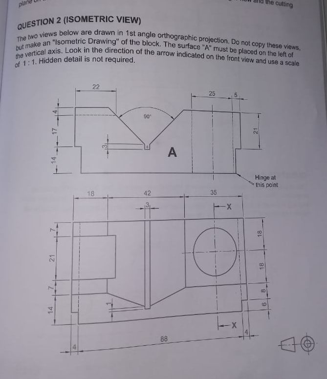 ERIN 15E yl
TION 2 (ISOMETRIC VIEW) b
wo views below are drawn in 1st angle orthogranpic oe.
panatosn isonet Drawing! of he ike a 0
ere? os in the direction of the dicated a De
§ £211 Gite dots nol require, row indicated onthe font view anu
Lo Se.
; | %_ gi
= he
= be
| lh
a |
LE TN teat
Lo 2 _
| El 3 x EL
Sl | |
i (5 .
i
sie fal Ew
< = -
3 w-(
88 el RN
4 £9
a E
A
This is AI generated Response.
Asked by: Rahul
Created at: 2026-01-11 03:45:43
Asked by: Rahul
Created at: 2026-01-11 03:45:43
Final Answer:
Rendered
Raw Text
Did you like this answer?
## Step-by-Step Solution for Isometric View Drawing
### **Question Review**
You are given two orthographic projections (front and top views) of a block. You are asked **not** to copy these views but to create an **isometric drawing** of the block, placing surface **A** to the left. The isometric view should be drawn to a scale of 1:1, and hidden details are not required.
---
### **Step 1: Interpret the Orthographic Projections**
#### **Front View (Top Image)**
- **Width (horizontal length):** 88 mm
- **Heights (vertical):** 14 mm (bottom), 17 mm (left), 21 mm (right), 25 mm (rightmost), 22 mm (leftmost)
- **Distinct Features:**
- Central V-groove (90° angle, 17 mm deep)
- Steps on both sides
#### **Top View (Bottom Image)**
- **Depth (front to back):** 42 mm (left), 35 mm (right)
- **Other Features:**
- Circular hole (right) with diameter 18 mm
- Rectangular slot (left) 18 mm wide
---
### **Step 2: Prepare for Isometric Drawing**
#### **What is Isometric Drawing?**
- All axes (X, Y, Z) are drawn at 120° to each other (usually with horizontal axes at 30° to the horizontal).
- True lengths are used along each axis.
#### **Orient the Block**
- Surface "A" must be on the left.
- Look in the direction of the arrow (from the front view).
---
### **Step 3: Draw the Bounding Box**
1. **Draw the base rectangle** in isometric:
- **Length:** 88 mm (X-axis)
- **Depth:** 42 mm + 35 mm = **77 mm** (Y-axis)
- **Height:** Highest point from front view = **25 mm** (Z-axis)
2. **Draw isometric axes:**
- X-axis: 30° right from horizontal (88 mm)
- Y-axis: 30° left from horizontal (77 mm)
- Z-axis: vertical (25 mm)
---
### **Step 4: Transfer Key Features**
#### **A. Step Heights and Positions**
- Left and right steps: 14 mm (base), then 17 mm (left) and 21 mm (right) vertically.
- Steps' top widths: 22 mm (left), 25 mm (right).
#### **B. Central V-Groove**
- Centered on block.
- 90° angle, 17 mm deep from top.
- Mark center, draw V-groove.
#### **C. Circular Hole**
- On right half, 18 mm diameter.
- 18 mm from front edge, centered in right part.
#### **D. Rectangular Slot (Left)**
- 18 mm wide, 21 mm from front edge.
- 18 mm from left edge (top view).
---
### **Step 5: Draw Features in Isometric**
1. **Draw outer block.**
2. **Draw steps on left and right sides.**
3. **Draw the central V-groove (projected in isometric).**
4. **Draw the rectangular slot on the left.**
5. **Draw the circular hole on the right (as an ellipse in isometric).**
6. **Add all dimensions using true lengths.**
---
### **Step 6: Finalize the Drawing**
- Use a ruler and set square for accurate 30° angles.
- Use ellipse templates or the "four-center method" for isometric circles (holes).
---
## **Final Answer (Summary Table)**
| Feature | Dimension(s) | Isometric Representation |
|------------------------|----------------------|------------------------------|
| Overall block | 88 × 77 × 25 mm | Main bounding box |
| Left step | 22 mm wide, 17 mm ht | Projected at left end |
| Right step | 25 mm wide, 21 mm ht | Projected at right end |
| Central V-groove | 90°, 17 mm deep | Centered, project in iso |
| Rectangular slot (left)| 18 mm wide | Projected as slot in iso |
| Circular hole (right) | 18 mm diameter | Ellipse in isometric view |
---
## **Isometric Drawing Example**
I am unable to draw images directly here, but follow these steps with your drawing tools for accuracy. Here's a simple **sketching sequence**:
1. Draw the isometric box.
2. Add steps at left and right ends.
3. Locate the center and sketch the V-groove.
4. Draw the rectangular slot on the left.
5. Draw the isometric ellipse for the circular hole on the right.
6. Check all dimensions with a ruler.
**Tip:** Refer to your orthographic projections at each step to ensure correct placement!
---
### **Conclusion**
This step-by-step process will help you create an accurate isometric drawing from the given orthographic projections. **Remember to keep surface "A" on the left, and use all the true dimensions!** If you need a hand-drawn example or further clarification, let me know!
📢 Instructions:
- Ask anything relatd to above question only.
- For new Question goto :