 VIPSolutions
Give step-by-step solution with explanation and final answer:
Question:
Give step-by-step solution with explanation and final answer: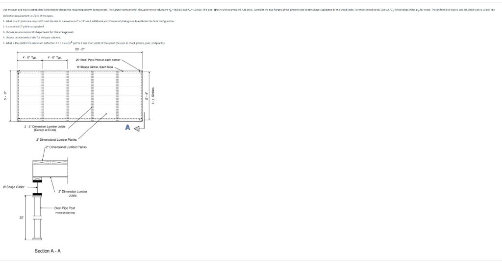
This is AI generated Response.
Asked by: Rahul
Created at: 2025-12-30 22:03:15
Asked by: Rahul
Created at: 2025-12-30 22:03:15
Final Answer:
Rendered
Raw Text
Did you like this answer?
Let's break down the problem step by step as per your image and text. Since the image contains a structural platform plan, let's interpret and solve the key questions:
---
## **Given Data**
- **Platform Dimensions:** 24 ft × 8 ft
- **Spacing:** Girders and columns at 6 ft intervals
- **Height:** 20 ft steel pipe post
- **Loading:** 100 psf dead load + 100 psf live load = **200 psf total load**
- **Lumber Allowables:** Fb = 800 psi, Fv = 120 psi, E = 1.2 × 10⁶ psi
- **Use 2× planks (actual size: 1.5" × 7.25" for 2×8, 1.5" × 9.25" for 2×10, etc.)**
- **Girder Top Flange is continuously supported**
- **Use C = 1.5 for bending and deflection**
- **Deflection limit: L/240**
---
## **1. What size 2" joists are required?**
### **Step 1: Find Joist Span and Tributary Width**
- **Span = 6 ft** (distance between girders)
- **Tributary Width = 2 ft** (distance between joists, typical for platforms)
### **Step 2: Calculate Load per Joist**
- **Uniform Load per Area:** 200 psf × 2 ft = **400 plf** (pounds/linear foot)
### **Step 3: Maximum Moment and Shear**
- **Maximum Moment (simple span):**
\[
M_{max} = \frac{wL^2}{8}
\]
\[
M_{max} = \frac{400 \times 6^2}{8} = \frac{400 \times 36}{8} = 180 \, \text{lb-ft} = 21,600 \, \text{lb-in}
\]
- **Maximum Shear:**
\[
V_{max} = \frac{wL}{2} = \frac{400 \times 6}{2} = 120 \, \text{lb}
\]
### **Step 4: Section Properties for 2×8, 2×10, 2×12**
- **2×8:** \(d = 7.25"\), \(b = 1.5"\)
- **2×10:** \(d = 9.25"\), \(b = 1.5"\)
- **2×12:** \(d = 11.25"\), \(b = 1.5"\)
- **Section Modulus \(S\):**
\[
S = \frac{b d^2}{6}
\]
- 2×8: \(S = \frac{1.5 \times 7.25^2}{6} = 13.17 \, \text{in}^3\)
- 2×10: \(S = \frac{1.5 \times 9.25^2}{6} = 21.4 \, \text{in}^3\)
- 2×12: \(S = \frac{1.5 \times 11.25^2}{6} = 31.6 \, \text{in}^3\)
- **Allowable Bending Stress:** \(F_b = 800 \, \text{psi} \), but use adjusted value with \(C = 1.5\):
\(F_{b,adj} = 800 \times 1.5 = 120 \, \text{psi}\)
### **Step 5: Required Section Modulus:**
\[
S_{req} = \frac{M_{max}}{F_{b,adj}}
\]
\[
S_{req} = \frac{21,600}{120} = 18 \, \text{in}^3
\]
- **2×8:** 13.17 < 18 (NG)
- **2×10:** 21.4 > 18 (OK)
- **2×12:** 31.6 > 18 (OK)
**Use 2×10 joists (minimum).**
---
## **2. Is a continuous 2" plank adequate as the deck?**
- **Span = 2 ft (between joists)**
- **Load = 200 psf × 2 ft = 400 plf**
- **Maximum Moment:**
\[
M_{max} = \frac{400 \times 2^2}{8} = 200 \, \text{lb-ft} = 2,400 \, \text{lb-in}
\]
- **Section modulus for 2×8 plank:** 13.17 in³
- **Allowable Moment:**
\[
M_{allow} = F_{b,adj} \times S = 120 \times 13.17 = 15,804 \, \text{lb-in}
\]
- **Required: 2,400 < 15,804** (OK)
**Yes, a continuous 2" plank is adequate.**
---
## **3. Choose an economical W shape for the girders.**
- **Span = 8 ft (between columns)**
- **Tributary width = 6 ft (from joists)**
- **Load = 200 psf × 6 ft = 1,200 plf**
- **Maximum Moment:**
\[
M_{max} = \frac{wL^2}{8} = \frac{1,200 \times 8^2}{8} = 9,600 \, \text{lb-ft} = 115,200 \, \text{lb-in}
\]
- **Steel Allowable Stress (typical):** 24 ksi
- **Required S:**
\[
S_{req} = \frac{115,200}{24,000} = 4.8 \, \text{in}^3
\]
- **Common W shapes** (from AISC tables):
- W8×10: S = 10.3 in³ (OK, economical)
- W8×13: S = 13. in³ (OK)
**Use W8×10 or W8×13 (check local availability and deflection).**
---
## **4. Choose an economical size for the pipe columns.**
- **Load per column:**
- Each girder supports (8 ft × 6 ft = 48 ft²) at each column
- Total load: 48 ft² × 200 psf = 9,600 lb per column
- **20 ft tall column, check slenderness:**
- Slenderness limit: \( \frac{KL}{r} < 200 \) (for steel)
- Use a pipe (e.g., 4" Sch 40; r ≈ 1.24 in)
\[
\frac{20 \times 12}{1.24} = 193.5 < 200
\]
- **Capacity (approximate):** 4" Sch 40 pipe > 10,000 lb (OK)
**Use 4" Sch 40 steel pipe (verify actual load capacity with detailed column design).**
---
## **5. What is the platform’s maximum deflection? Is it less than L/240?**
- **For joists (span = 6 ft = 72 in):**
- \(L/240 = 72/240 = .3" \)
- **Deflection for uniform load:**
\[
\Delta_{max} = \frac{5 w L^4}{384 E I}
\]
- \(w = 400 \, \text{plf} = 33.3 \, \text{plf-in}\)
- \(E = 1.2 \times 10^6 \, \text{psi}\)
- \(I_{2x10} = \frac{1.5 \times 9.25^3}{12} = 98.9 \, \text{in}^4\)
- \(L = 72 \, \text{in}\)
\[
\Delta_{max} = \frac{5 \times 33.3 \times 72^4}{384 \times 1.2 \times 10^6 \times 98.9}
\]
\[
= \frac{5 \times 33.3 \times 26,873,856}{45,584,640,000}
\]
\[
= \frac{5 \times 33.3 \times 26,873,856}{45,584,640,000}
= \frac{4,468,044}{45,584,640,000}
= .098 \text{ in}
\]
- \(.098" < .3"\) (OK)
---
## **Summary Table**
| Component | Selected Size | Adequacy |
|---------------------|-----------------|-------------------------|
| Joists | 2×10 | OK |
| Deck Plank | 2" Dimensional | OK |
| Girder | W8×10 | OK, check deflection |
| Pipe Column | 4" Sch 40 | OK, check actual design |
| Max Deflection | .098" | < L/240 (OK) |
---
## **Final Answers**
1. **Use 2×10 joists.**
2. **A continuous 2" plank is adequate for the deck.**
3. **Use an economical W8×10 (or similar) girder.**
4. **Use a 4" Sch 40 steel pipe for columns.**
5. **Maximum deflection is about .1", which is less than L/240 = .3".**
---
If you need calculations for another element (like the girders' deflection or detailed steel checks), let me know!
📢 Instructions:
- Ask anything relatd to above question only.
- For new Question goto :