 VIPSolutions
Give step-by-step solution with explanation and final answer: Think like a real problem solver and explain me logic for:o* prdy50000pV| yy “I [>o 2 Us Pav 33000V «2 mriy 50000V D us | Po 8 D o © mfys0000pv] 2 fglv3:3000V 2 = I ~ LED1 [4]
Question:
Give step-by-step solution with explanation and final answer:
Think like a real problem solver and explain me logic for: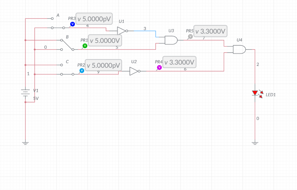 o* prdy50000pV| yy
“I [>o 2 Us Pav 33000V
«2 mriy 50000V D us
| Po 8 D
o © mfys0000pv] 2 fglv3:3000V 2
= I ~ LED1
[4]
This is AI generated Response.
Asked by: Francis
Created at: 2025-12-28 21:11:56
Asked by: Francis
Created at: 2025-12-28 21:11:56
Final Answer:
Rendered
Raw Text
Did you like this answer?
# Step-by-Step Solution and Logic
Let's analyze logic circuit step by step. We'll track each input, gate, and output to understand when the LED turns ON.
---
## **1. Identify the Inputs and Their States**
- **Switch A** = (connected to ground, **logic **)
- **Switch B** = 1 (connected to +5V, **logic 1**)
- **Switch C** = (connected to ground, **logic **)
---
## **2. Gate-by-Gate Analysis**
### **A. Inverter U1 (NOT Gate)**
- **Input:** A =
- **Output:** U1 = **NOT() = 1**
### **B. Inverter U2 (NOT Gate)**
- **Input:** C =
- **Output:** U2 = **NOT() = 1**
### **C. AND Gate U3**
- **Inputs:**
- Output of U1 (A') = 1
- B = 1
- **Output:** U3 = **A' AND B = 1 AND 1 = 1**
### **D. AND Gate U4**
- **Inputs:**
- Output of U3 = 1
- Output of U2 (C') = 1
- **Output:** U4 = **U3 AND C' = 1 AND 1 = 1**
---
## **3. LED Status**
- **LED1** is connected to the output of U4.
- Since U4 outputs **1 (HIGH, 3.3V)**, **LED1 turns ON**.
---
## **4. Logic Explanation**
- The circuit logic can be summarized as:
- LED1 = (NOT A AND B) AND (NOT C)
- With A = , B = 1, C = :
- NOT A = 1, NOT C = 1, so LED1 = (1 AND 1) AND 1 = 1
---
## **5. Final Answer**
### **Final State**
- **LED1 is ON.**
---
## **Summary Table**
| Switch | Value | After NOT | Used in AND gates | Final Output |
|--------|-------|-----------|-------------------|--------------|
| A | | 1 | U3 | 1 |
| B | 1 | - | U3 | 1 |
| C | | 1 | U4 | 1 |
---
### **Conclusion**
- **Logic Statement:** LED1 = (NOT A AND B) AND (NOT C)
- **With switches A=, B=1, C=, the LED1 is ON.**
---
**If you want to see the output for other switch combinations, let me know!**
📢 Instructions:
- Ask anything relatd to above question only.
- For new Question goto :